Dell PowerEdge C6300 Dell PowerEdge C6320 Owners Manual - Page 74
Installing the PERC card
 |
View all Dell PowerEdge C6300 manuals
Add to My Manuals
Save this manual to your list of manuals |
Page 74 highlights
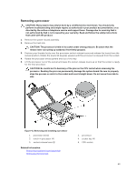
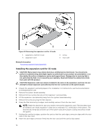
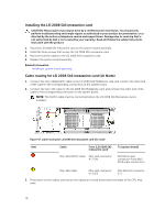
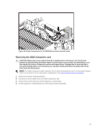
Installing the PERC card CAUTION: Many repairs may only be done by a certified service technician. You should only perform troubleshooting and simple repairs as authorized in your product documentation, or as directed by the online or telephone service and support team. Damage due to servicing that is not authorized by Dell is not covered by your warranty. Read and follow the safety instructions that came with the product. 1. Turn off the system, including any attached peripherals, and disconnect the system from the electrical outlet. NOTE: It is recommended that you always use a static mat and static strap while working on components in the interior of the system. 2. Open the system. 3. Locate the PERC card connector on the system board and align one end of the card with the card holder on the system board. CAUTION: To prevent damage to the card, you must hold the card by its edges only. 4. Lower the other end of the card into the card holder on the system board. 5. Connect the storage controller cable: a. Grasp the cable on both sides of the cable connector, and connect to the PERC card. b. Attach the two screws to secure the cable to the card. 6. Connect the SAS data cable connector to the card. NOTE: It is recommended that you always use a static mat and static strap while working on components in the interior of the system. 7. Route the SAS data cable through the clip on the card and through the channel on the inner side of the chassis. 8. Attach the connector labeled "SAS A" to connector SAS A on the backplane, and attach the connector labeled "SAS B" to connector SAS B on the backplane. 9. Close the system. 10. Reconnect the system to its electrical outlet and turn the system on, including any attached peripherals. 74
-
 1
1 -
2
-
3
-
4
-
5
-
6
-
7
-
8
-
9
-
10
-
11
-
12
-
13
-
14
-
15
-
16
-
17
-
18
-
19
-
20
-
21
-
22
-
23
-
24
-
25
-
26
-
27
-
28
-
29
-
30
-
31
-
32
-
33
-
34
-
35
-
36
-
37
-
38
-
39
-
40
-
41
-
42
-
43
-
44
-
45
-
46
-
47
-
48
-
49
-
50
-
51
-
52
-
53
-
54
-
55
-
56
-
57
-
58
-
59
-
60
-
61
-
62
-
63
-
64
-
65
-
66
-
67
-
68
-
 69
69 -
 70
70 -
 71
71 -
 72
72 -
 73
73 -
 74
74 -
 75
75 -
 76
76 -
 77
77 -
 78
78 -
 79
79 -
80
-
81
-
82
-
83
-
84
-
85
-
86
-
87
-
88
-
89
-
90
-
91
-
92
-
93
-
94
-
95
-
96
-
97
-
98
-
99
-
100
-
101
-
102
-
103
-
104
-
105
-
106
-
107
-
108
-
109
-
110
-
111
-
112
-
113
-
114
-
115
-
116
-
117
-
118
-
119
-
120
-
121
-
122
-
123
-
124
-
125
-
126
-
127
-
128
-
129
-
130
-
131
-
132
-
133
-
134
-
135
-
136
-
137
-
138
-
139
-
140
-
141
-
142
-
143
-
144
-
145
-
146
-
147
-
148
 |
 |