Dell PowerEdge C6300 Dell PowerEdge C6320 Owners Manual - Page 14
Back panel features and indicators, Up to 1400 W AC, 1600 W AC
 |
View all Dell PowerEdge C6300 manuals
Add to My Manuals
Save this manual to your list of manuals |
Page 14 highlights
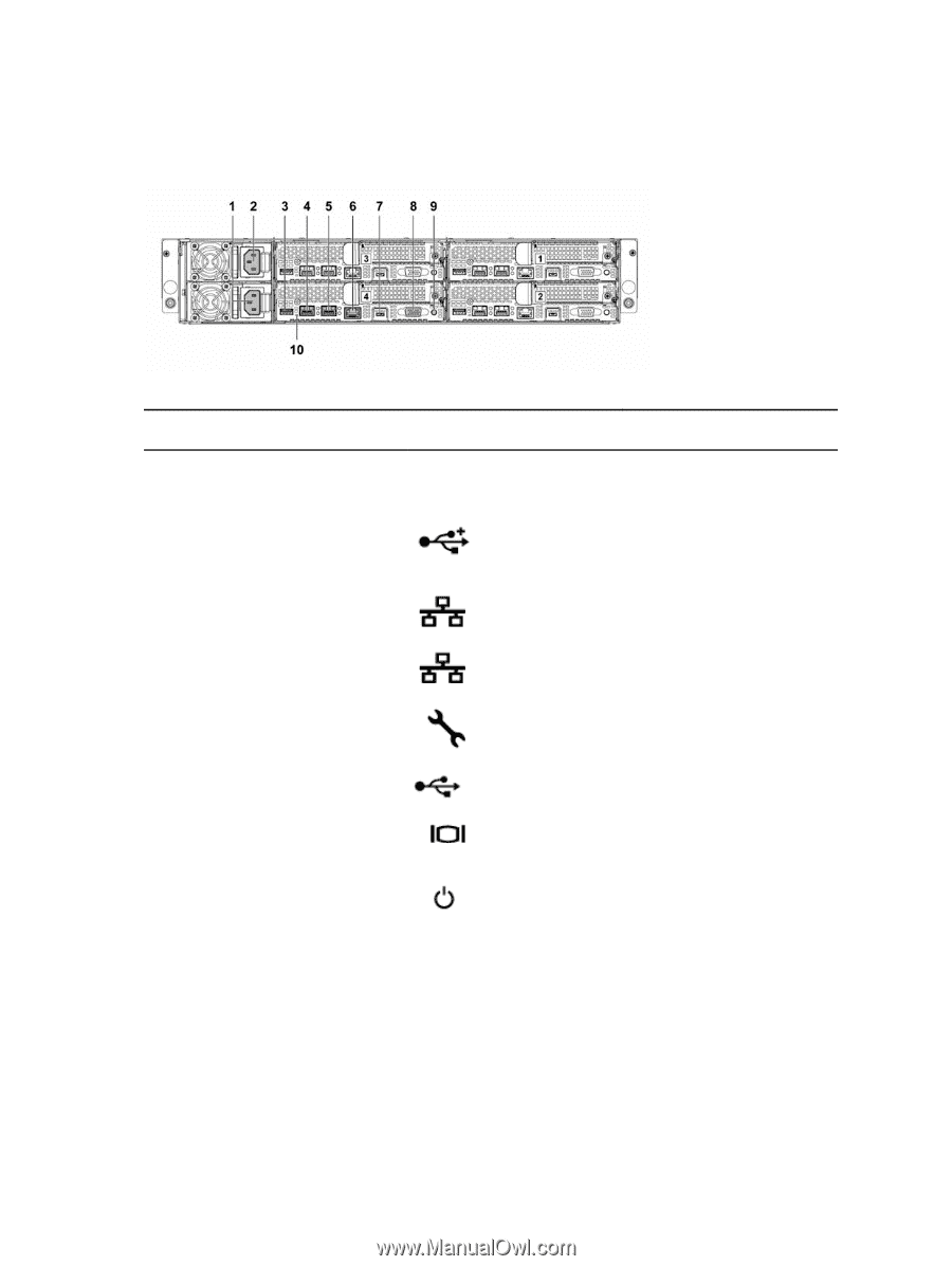
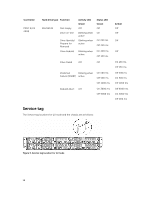
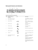
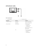
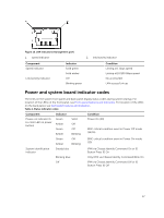
Back panel features and indicators Figure 9. Back panel with four system boards Item Indicator, button, or connector 1 Power supply unit (PSU2) 2 Power supply unit (PSU1) Icon 3 Single USB port 4 10G NIC 1 port 5 10G NIC 2 port 6 Management port 7 USB to serial port 8 VGA port 9 Power button/power and system LED 14 Description Up to 1400 W AC, 1600 W AC, or 1400 HVDC power supply units. Connect USB devices to the system. The ports are USB 3.0compliant. Embedded 10G NIC connectors. Embedded 10G NIC connectors. Dedicated management port. Connects the system to a host. Connects a VGA display to the system. The power-on indicator turns to green when the system power is on. The power-on indicator turns to amber when the system critical event occurs. The power button controls the DC power supply output to the system.
-
 1
1 -
2
-
3
-
4
-
5
-
6
-
7
-
8
-
 9
9 -
 10
10 -
 11
11 -
 12
12 -
 13
13 -
 14
14 -
 15
15 -
 16
16 -
 17
17 -
 18
18 -
 19
19 -
20
-
21
-
22
-
23
-
24
-
25
-
26
-
27
-
28
-
29
-
30
-
31
-
32
-
33
-
34
-
35
-
36
-
37
-
38
-
39
-
40
-
41
-
42
-
43
-
44
-
45
-
46
-
47
-
48
-
49
-
50
-
51
-
52
-
53
-
54
-
55
-
56
-
57
-
58
-
59
-
60
-
61
-
62
-
63
-
64
-
65
-
66
-
67
-
68
-
69
-
70
-
71
-
72
-
73
-
74
-
75
-
76
-
77
-
78
-
79
-
80
-
81
-
82
-
83
-
84
-
85
-
86
-
87
-
88
-
89
-
90
-
91
-
92
-
93
-
94
-
95
-
96
-
97
-
98
-
99
-
100
-
101
-
102
-
103
-
104
-
105
-
106
-
107
-
108
-
109
-
110
-
111
-
112
-
113
-
114
-
115
-
116
-
117
-
118
-
119
-
120
-
121
-
122
-
123
-
124
-
125
-
126
-
127
-
128
-
129
-
130
-
131
-
132
-
133
-
134
-
135
-
136
-
137
-
138
-
139
-
140
-
141
-
142
-
143
-
144
-
145
-
146
-
147
-
148
 |
 |