Dell PowerEdge C6300 Dell PowerEdge C6320 Owners Manual - Page 114
Expander-card connector 2
 |
View all Dell PowerEdge C6300 manuals
Add to My Manuals
Save this manual to your list of manuals |
Page 114 highlights
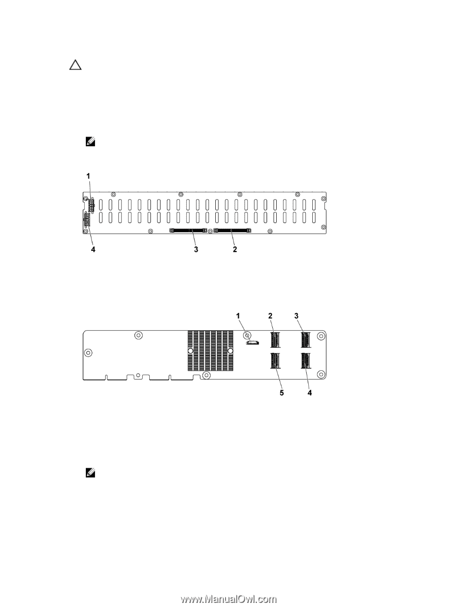
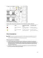
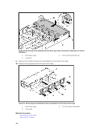
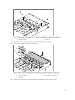
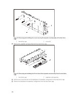
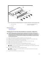
CAUTION: You must note the number of each hard drive and temporarily label them before removal so that you can replace them in the same locations. 1. It is recommended to turn off the system, including any attached peripherals, and disconnect the system from its electrical outlet 2. Remove all the hard drives. 3. Open the system. 4. Disconnect all the cables from the backplane and expander card. NOTE: Observe the routing of the cable on the chassis as you remove them from the system. You must route these cables properly when you replace them to prevent the cables from being pinched or crimped. Figure 88. Back view of the 2.5 inch hard-drive backplane for expander configuration 1. backplane power connector for power supply 1 3. Expander-card connector 2 2. Expander-card connector 1 4. backplane power connector for power supply 2 Figure 89. Top view of the expander card 1. Power control connector 3. mini-SAS connector (12~15) 5. mini-SAS connector (0~3) 2. mini-SAS connector (4~7) 4. mini-SAS connector (8~11) 5. Disconnect front panel cables from the power distribution board. NOTE: Observe the routing of the cable on the chassis as you remove them from the system. You must route these cables properly when you replace them to prevent the cables from being pinched or crimped. 6. Remove the screws that secure the hard-drive cage to the chassis. 114
-
 1
1 -
2
-
3
-
4
-
5
-
6
-
7
-
8
-
9
-
10
-
11
-
12
-
13
-
14
-
15
-
16
-
17
-
18
-
19
-
20
-
21
-
22
-
23
-
24
-
25
-
26
-
27
-
28
-
29
-
30
-
31
-
32
-
33
-
34
-
35
-
36
-
37
-
38
-
39
-
40
-
41
-
42
-
43
-
44
-
45
-
46
-
47
-
48
-
49
-
50
-
51
-
52
-
53
-
54
-
55
-
56
-
57
-
58
-
59
-
60
-
61
-
62
-
63
-
64
-
65
-
66
-
67
-
68
-
69
-
70
-
71
-
72
-
73
-
74
-
75
-
76
-
77
-
78
-
79
-
80
-
81
-
82
-
83
-
84
-
85
-
86
-
87
-
88
-
89
-
90
-
91
-
92
-
93
-
94
-
95
-
96
-
97
-
98
-
99
-
100
-
101
-
102
-
103
-
104
-
105
-
106
-
107
-
108
-
 109
109 -
 110
110 -
 111
111 -
 112
112 -
 113
113 -
 114
114 -
 115
115 -
 116
116 -
 117
117 -
 118
118 -
 119
119 -
120
-
121
-
122
-
123
-
124
-
125
-
126
-
127
-
128
-
129
-
130
-
131
-
132
-
133
-
134
-
135
-
136
-
137
-
138
-
139
-
140
-
141
-
142
-
143
-
144
-
145
-
146
-
147
-
148
 |
 |