Dell PowerEdge C6300 Dell PowerEdge C6320 Owners Manual - Page 87
Removing the memory modules
 |
View all Dell PowerEdge C6300 manuals
Add to My Manuals
Save this manual to your list of manuals |
Page 87 highlights
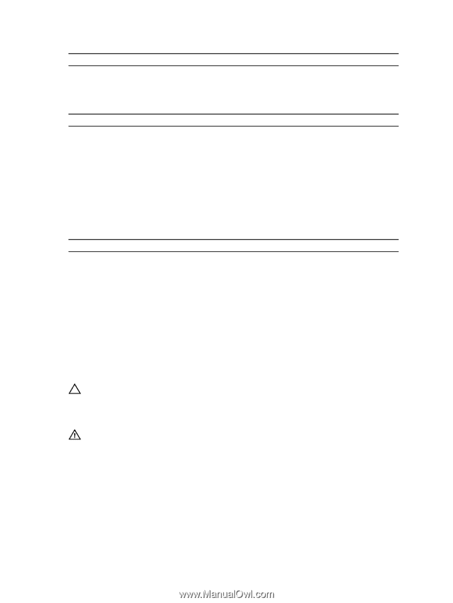
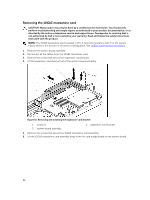
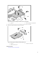
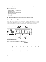
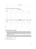
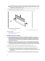
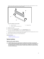
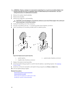
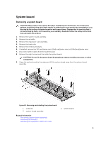
Processor 1 6 √ √ √ √ √ ‒ √ ‒ 8 √ √ √ √ √ √ √ √ Table 3. Memory module configurations for dual processors Memory module CHA CHB Processor 1 CHC A1 A5 A2 A6 A3 A7 2 √ ‒ ‒ ‒ ‒ ‒ 6 √ ‒ √ ‒ √ ‒ 8 √ ‒ √ ‒ √ ‒ 12 √ √ √ √ √ ‒ 16 √ √ √ √ √ √ CHD A4 A8 ‒ ‒ ‒ ‒ √ ‒ √ ‒ √ √ Memory module 2 6 8 12 16 CHA B1 B5 √ ‒ √ ‒ √ ‒ √ √ √ √ CHB Processor 2 CHC B2 B6 B3 B7 ‒ ‒ ‒ ‒ √ ‒ √ ‒ √ ‒ √ ‒ √ √ √ ‒ √ √ √ √ CHD B4 B8 ‒ ‒ ‒ ‒ √ ‒ √ ‒ √ √ Removing the memory modules CAUTION: Many repairs may only be done by a certified service technician. You should only perform troubleshooting and simple repairs as authorized in your product documentation, or as directed by the online or telephone service and support team. Damage due to servicing that is not authorized by Dell is not covered by your warranty. Read and follow the safety instructions that came with the product. WARNING: The memory modules are hot to the touch for some time after the system has been powered down. Allow time for the memory modules to cool before handling them. Handle the memory modules by the card edges and avoid touching the components on the memory module. 1. Remove the system-board assembly. 2. Remove the air baffle. 3. Locate the memory module sockets. 87
-
 1
1 -
2
-
3
-
4
-
5
-
6
-
7
-
8
-
9
-
10
-
11
-
12
-
13
-
14
-
15
-
16
-
17
-
18
-
19
-
20
-
21
-
22
-
23
-
24
-
25
-
26
-
27
-
28
-
29
-
30
-
31
-
32
-
33
-
34
-
35
-
36
-
37
-
38
-
39
-
40
-
41
-
42
-
43
-
44
-
45
-
46
-
47
-
48
-
49
-
50
-
51
-
52
-
53
-
54
-
55
-
56
-
57
-
58
-
59
-
60
-
61
-
62
-
63
-
64
-
65
-
66
-
67
-
68
-
69
-
70
-
71
-
72
-
73
-
74
-
75
-
76
-
77
-
78
-
79
-
80
-
81
-
 82
82 -
 83
83 -
 84
84 -
 85
85 -
 86
86 -
 87
87 -
 88
88 -
 89
89 -
 90
90 -
 91
91 -
 92
92 -
93
-
94
-
95
-
96
-
97
-
98
-
99
-
100
-
101
-
102
-
103
-
104
-
105
-
106
-
107
-
108
-
109
-
110
-
111
-
112
-
113
-
114
-
115
-
116
-
117
-
118
-
119
-
120
-
121
-
122
-
123
-
124
-
125
-
126
-
127
-
128
-
129
-
130
-
131
-
132
-
133
-
134
-
135
-
136
-
137
-
138
-
139
-
140
-
141
-
142
-
143
-
144
-
145
-
146
-
147
-
148
 |
 |