Dell PowerEdge C6300 Dell PowerEdge C6320 Owners Manual - Page 138
Backplane connectors, 3.5 inch hard-drive direct backplane
 |
View all Dell PowerEdge C6300 manuals
Add to My Manuals
Save this manual to your list of manuals |
Page 138 highlights
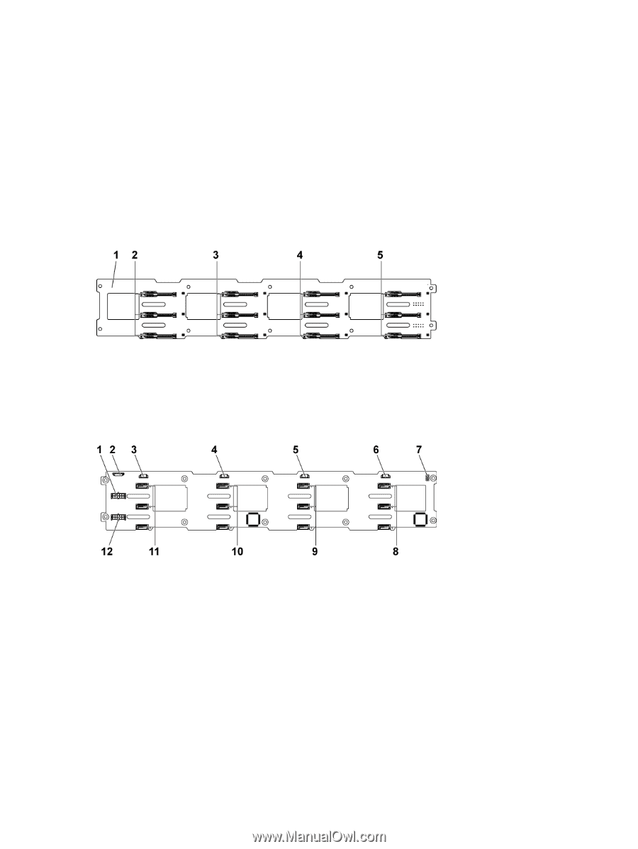
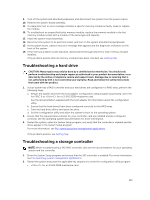
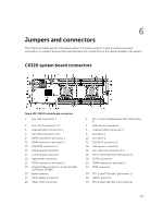
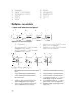
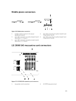
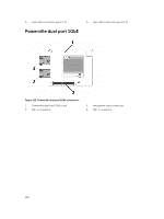
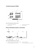
31. Power button 33. Internal TTL COM Connector 35. LAN Management Connector 37. LAN 2 LED 39. LAN 1 LED 41. UID LED 32. VGA port 34. USB to Serial Port 36. Management Port 38. LAN 2 Port 40. LAN 1 Port Backplane connectors 3.5 inch hard-drive direct backplane Figure 103. Front view of the backplane 1. 3.5 inch backplane 3. hard drive connectors 1, 2 and 3 for system board 2 (from top to bottom) 5. hard drive connectors 1, 2 and 3 for system board 4 (from top to bottom) 2. hard drive connectors 1, 2 and 3 for system board 1 (from top to bottom) 4. hard drive connectors 1, 2 and 3 for system board 3 (from top to bottom) Figure 104. Back view of the backplane 1. backplane power connector for power supply 2. 1x8pin fan controller board connector unit 1 3. SGPIO connector 4 for system board 4 4. SGPIO connector 3 for system board 3 5. SGPIO connector 2 for system board 2 6. SGPIO connector 1 for system board 1 7. backplane jumper 8. SATA2 and SAS connectors 1, 2 and 3 for system board 1 (from top to bottom) 9. SATA2 and SAS connectors 1, 2 and 3 for system board 2 (from top to bottom) 10. SATA2 and SAS connectors 1, 2 and 3 for system board 3 (from top to bottom) 11. SATA2 and SAS connectors 1, 2 and 3 for system board 4 (from top to bottom) 12. backplane power connector for power supply unit 2 138
-
 1
1 -
2
-
3
-
4
-
5
-
6
-
7
-
8
-
9
-
10
-
11
-
12
-
13
-
14
-
15
-
16
-
17
-
18
-
19
-
20
-
21
-
22
-
23
-
24
-
25
-
26
-
27
-
28
-
29
-
30
-
31
-
32
-
33
-
34
-
35
-
36
-
37
-
38
-
39
-
40
-
41
-
42
-
43
-
44
-
45
-
46
-
47
-
48
-
49
-
50
-
51
-
52
-
53
-
54
-
55
-
56
-
57
-
58
-
59
-
60
-
61
-
62
-
63
-
64
-
65
-
66
-
67
-
68
-
69
-
70
-
71
-
72
-
73
-
74
-
75
-
76
-
77
-
78
-
79
-
80
-
81
-
82
-
83
-
84
-
85
-
86
-
87
-
88
-
89
-
90
-
91
-
92
-
93
-
94
-
95
-
96
-
97
-
98
-
99
-
100
-
101
-
102
-
103
-
104
-
105
-
106
-
107
-
108
-
109
-
110
-
111
-
112
-
113
-
114
-
115
-
116
-
117
-
118
-
119
-
120
-
121
-
122
-
123
-
124
-
125
-
126
-
127
-
128
-
129
-
130
-
131
-
132
-
 133
133 -
 134
134 -
 135
135 -
 136
136 -
 137
137 -
 138
138 -
 139
139 -
 140
140 -
 141
141 -
 142
142 -
 143
143 -
144
-
145
-
146
-
147
-
148
 |
 |