Dell PowerEdge C6300 Dell PowerEdge C6320 Owners Manual - Page 86
Memory slot features, Supported memory module configuration, Max. capacities: 256GB with 16GB RDIMM
 |
View all Dell PowerEdge C6300 manuals
Add to My Manuals
Save this manual to your list of manuals |
Page 86 highlights
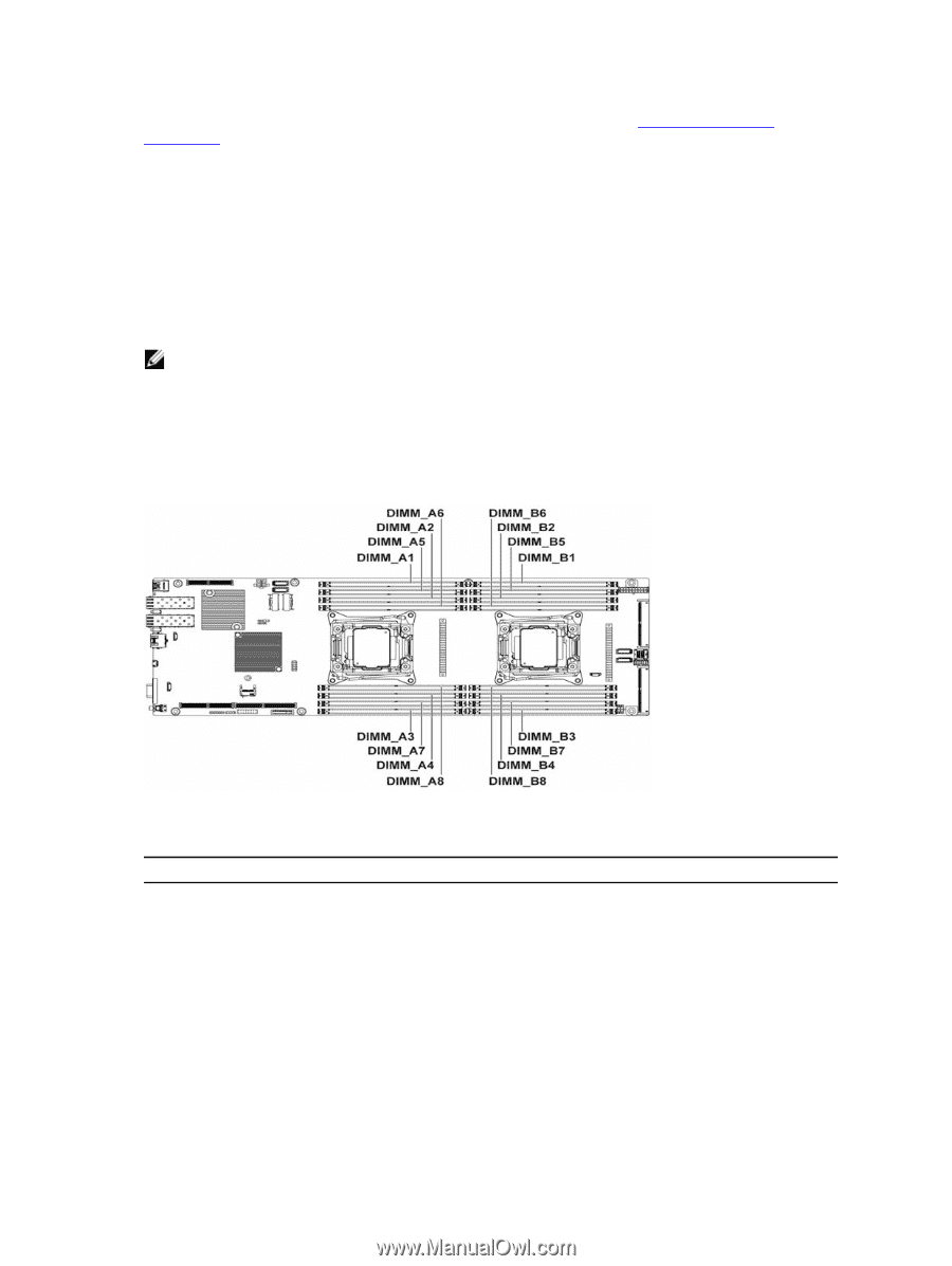
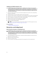
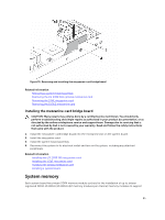
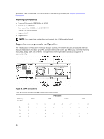
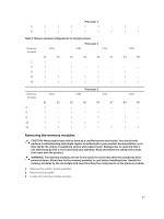
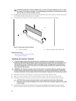
processor 1 and processor 2. For the location of the memory modules, see C6320 system board connectors. Memory slot features • Support 8 channels, 16 RDIMMs of DDR4 • Speed up to 2133MT/s • Max. capacities: 256GB with 16GB RDIMM 256GB with 32GB RDIMM • Support DDR4 • Support ECC NOTE: Linux operating system does not support the S4 (hibernation) mode. Supported memory module configuration For the sequence of the sixteen memory-module sockets, The system requires at least one memory module installed on processor 1's DIMM slot 1 in order to be booted up. When you insert the memory module(s), always start with CHA_A1. The optimized memory module installation sequence is 1/2/3/4/5/6/7/8. Figure 56. DIMM slot locations Table 2. Memory module configurations for single processor Processor 1 Memory module CHA CHB CHC A1 A5 A2 A6 A3 A7 1 √ ‒ ‒ ‒ ‒ ‒ 2 √ ‒ √ ‒ ‒ ‒ 3 √ ‒ √ ‒ √ ‒ 4 √ ‒ √ ‒ √ ‒ CHD A4 A8 ‒ ‒ ‒ ‒ ‒ ‒ √ ‒ 86
-
 1
1 -
2
-
3
-
4
-
5
-
6
-
7
-
8
-
9
-
10
-
11
-
12
-
13
-
14
-
15
-
16
-
17
-
18
-
19
-
20
-
21
-
22
-
23
-
24
-
25
-
26
-
27
-
28
-
29
-
30
-
31
-
32
-
33
-
34
-
35
-
36
-
37
-
38
-
39
-
40
-
41
-
42
-
43
-
44
-
45
-
46
-
47
-
48
-
49
-
50
-
51
-
52
-
53
-
54
-
55
-
56
-
57
-
58
-
59
-
60
-
61
-
62
-
63
-
64
-
65
-
66
-
67
-
68
-
69
-
70
-
71
-
72
-
73
-
74
-
75
-
76
-
77
-
78
-
79
-
80
-
 81
81 -
 82
82 -
 83
83 -
 84
84 -
 85
85 -
 86
86 -
 87
87 -
 88
88 -
 89
89 -
 90
90 -
 91
91 -
92
-
93
-
94
-
95
-
96
-
97
-
98
-
99
-
100
-
101
-
102
-
103
-
104
-
105
-
106
-
107
-
108
-
109
-
110
-
111
-
112
-
113
-
114
-
115
-
116
-
117
-
118
-
119
-
120
-
121
-
122
-
123
-
124
-
125
-
126
-
127
-
128
-
129
-
130
-
131
-
132
-
133
-
134
-
135
-
136
-
137
-
138
-
139
-
140
-
141
-
142
-
143
-
144
-
145
-
146
-
147
-
148
 |
 |