Dell PowerEdge C6300 Dell PowerEdge C6320 Owners Manual - Page 123
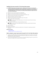
Removing the sensor board for 2.5 inch hard-drive system
 |
View all Dell PowerEdge C6300 manuals
Add to My Manuals
Save this manual to your list of manuals |
Page 123 highlights
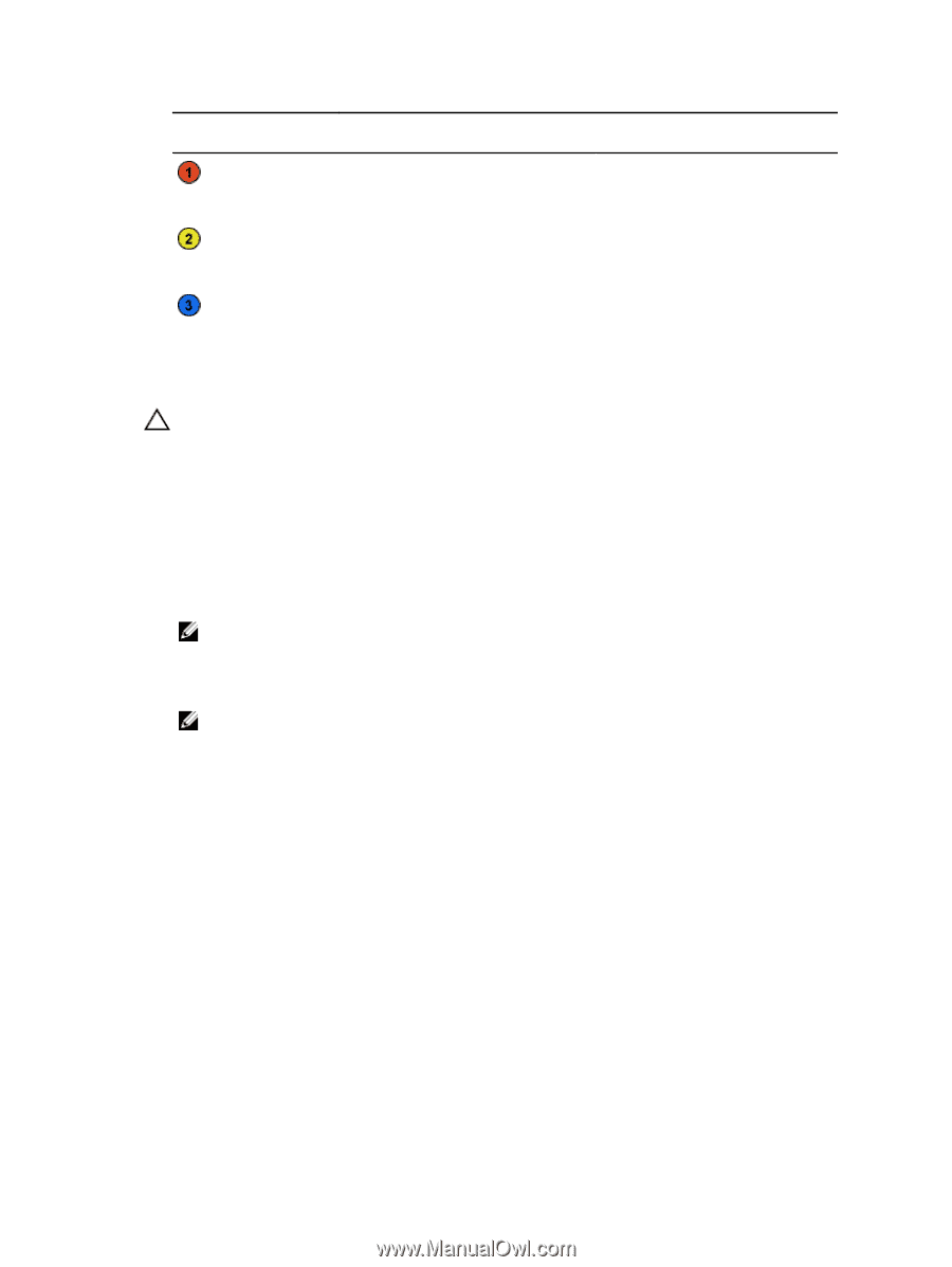
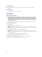
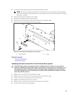
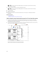
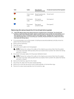
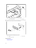
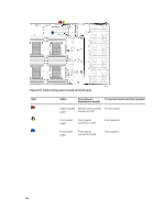
Item Cable From (power To (sensor board and front panels) distribution board) Sensor board Sensor board power Sensor board cable connector (J1) Front panel cable Front panel connector (J16) Front panel 2 Front panel cable Front panel connector (J18) Front panel 1 Removing the sensor board for 2.5 inch hard-drive system CAUTION: Many repairs may only be done by a certified service technician. You should only perform troubleshooting and simple repairs as authorized in your product documentation, or as directed by the online or telephone service and support team. Damage due to servicing that is not authorized by Dell is not covered by your warranty. Read and follow the safety instructions that came with the product. 1. It is recommended to turn off the system, including any attached peripherals, and disconnect the system from the electrical outlet. 2. Remove all the hard drives. 3. Open the system. 4. Disconnect all the cables from the backplane. NOTE: Observe the routing of the cable on the chassis as you remove them from the system. You must route these cables properly when you replace them to prevent the cables from being pinched or crimped. 5. Disconnect front panel cables from the power distribution board. NOTE: Observe the routing of the cable on the chassis as you remove them from the system. You must route these cables properly when you replace them to prevent the cables from being pinched or crimped. 6. Remove the hard drive cage from the chassis. 7. Disconnect the cable from the sensor board assembly. 8. Remove the screw that secures the sensor board assembly to the hard drive cage. 9. Remove the sensor board assembly from the hard drive cage. 123
-
 1
1 -
2
-
3
-
4
-
5
-
6
-
7
-
8
-
9
-
10
-
11
-
12
-
13
-
14
-
15
-
16
-
17
-
18
-
19
-
20
-
21
-
22
-
23
-
24
-
25
-
26
-
27
-
28
-
29
-
30
-
31
-
32
-
33
-
34
-
35
-
36
-
37
-
38
-
39
-
40
-
41
-
42
-
43
-
44
-
45
-
46
-
47
-
48
-
49
-
50
-
51
-
52
-
53
-
54
-
55
-
56
-
57
-
58
-
59
-
60
-
61
-
62
-
63
-
64
-
65
-
66
-
67
-
68
-
69
-
70
-
71
-
72
-
73
-
74
-
75
-
76
-
77
-
78
-
79
-
80
-
81
-
82
-
83
-
84
-
85
-
86
-
87
-
88
-
89
-
90
-
91
-
92
-
93
-
94
-
95
-
96
-
97
-
98
-
99
-
100
-
101
-
102
-
103
-
104
-
105
-
106
-
107
-
108
-
109
-
110
-
111
-
112
-
113
-
114
-
115
-
116
-
117
-
 118
118 -
 119
119 -
 120
120 -
 121
121 -
 122
122 -
 123
123 -
 124
124 -
 125
125 -
 126
126 -
 127
127 -
 128
128 -
129
-
130
-
131
-
132
-
133
-
134
-
135
-
136
-
137
-
138
-
139
-
140
-
141
-
142
-
143
-
144
-
145
-
146
-
147
-
148
 |
 |