Dell PowerEdge C6300 Dell PowerEdge C6320 Owners Manual - Page 17
Power and system board indicator codes, IPMI via Chassis Identify Command Off or ID
 |
View all Dell PowerEdge C6300 manuals
Add to My Manuals
Save this manual to your list of manuals |
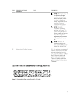
Page 17 highlights
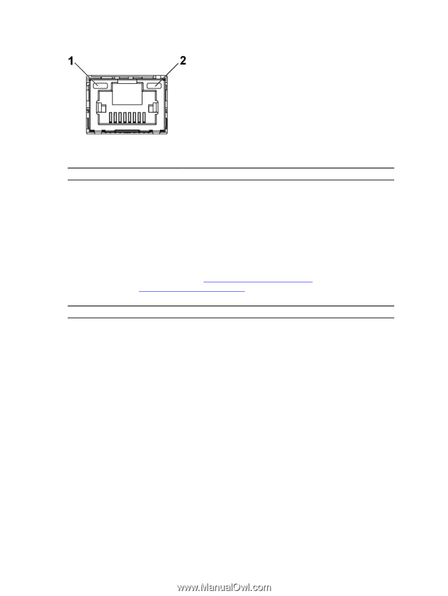
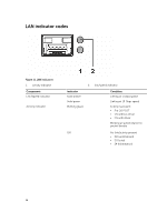
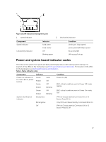
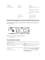
Figure 12. LAN indicators (management port) 1. speed indicator 2. link/activity indicator Component Speed indicator Link/activity indicator Indicator Solid green Solid amber Off Blinking green Condition Linking at 1 Gbps speed Linking at 10/100 Mbps speed No access/Idle LAN access/Link up Power and system board indicator codes The LEDs on the system front panel and back panel display status codes during system startup. For location of the LEDs on the front panel, see Front-panel features and indicators. For location of the LEDs on the back panel, see Back panel features and indicators. Table 1. Status indicator codes Component Power-on indicator (A bi-color LED on power button) Indicator Green Amber Green Amber Solid Off Off Blinking Condition Power On (S0) BMC critical condition event in Power Off mode (S4/S5) Green Amber Off Blinking BMC critical condition event in Power On mode (S0) System identification indicator Steady blue IPMI via Chassis Identify Command On or ID Button Press ID On Blinking blue Only IPMI via Chassis Identify Command Blink On Off IPMI via Chassis Identify Command Off or ID Button Press ID Off 17
-
 1
1 -
2
-
3
-
4
-
5
-
6
-
7
-
8
-
9
-
10
-
11
-
 12
12 -
 13
13 -
 14
14 -
 15
15 -
 16
16 -
 17
17 -
 18
18 -
 19
19 -
 20
20 -
 21
21 -
 22
22 -
23
-
24
-
25
-
26
-
27
-
28
-
29
-
30
-
31
-
32
-
33
-
34
-
35
-
36
-
37
-
38
-
39
-
40
-
41
-
42
-
43
-
44
-
45
-
46
-
47
-
48
-
49
-
50
-
51
-
52
-
53
-
54
-
55
-
56
-
57
-
58
-
59
-
60
-
61
-
62
-
63
-
64
-
65
-
66
-
67
-
68
-
69
-
70
-
71
-
72
-
73
-
74
-
75
-
76
-
77
-
78
-
79
-
80
-
81
-
82
-
83
-
84
-
85
-
86
-
87
-
88
-
89
-
90
-
91
-
92
-
93
-
94
-
95
-
96
-
97
-
98
-
99
-
100
-
101
-
102
-
103
-
104
-
105
-
106
-
107
-
108
-
109
-
110
-
111
-
112
-
113
-
114
-
115
-
116
-
117
-
118
-
119
-
120
-
121
-
122
-
123
-
124
-
125
-
126
-
127
-
128
-
129
-
130
-
131
-
132
-
133
-
134
-
135
-
136
-
137
-
138
-
139
-
140
-
141
-
142
-
143
-
144
-
145
-
146
-
147
-
148
 |
 |