Dell PowerEdge C6300 Dell PowerEdge C6320 Owners Manual - Page 117
Installing the 2.5-inch hard drive backplane for expander configuration
 |
View all Dell PowerEdge C6300 manuals
Add to My Manuals
Save this manual to your list of manuals |
Page 117 highlights
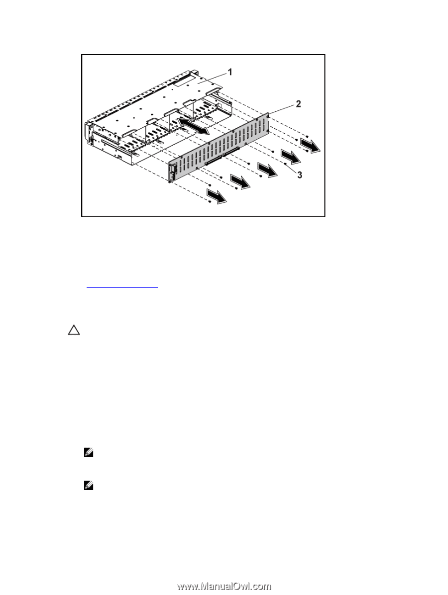
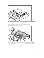
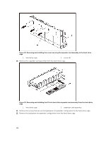
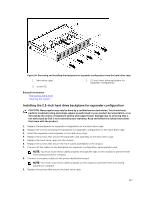
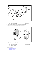
Figure 94. Removing and installing the backplane for expander configuration from the hard-drive cage 1. hard drive cage 3. screw (11) 2. 2.5 inch hard-drive backplane for expander configuration Related Information Removing a hard-drive Opening the system Installing the 2.5-inch hard drive backplane for expander configuration CAUTION: Many repairs may only be done by a certified service technician. You should only perform troubleshooting and simple repairs as authorized in your product documentation, or as directed by the online or telephone service and support team. Damage due to servicing that is not authorized by Dell is not covered by your warranty. Read and follow the safety instructions that came with the product. 1. Replace the backplane for expander configuration to the hard-drive cage. 2. Replace the screws securing the backplane for expander configuration to the hard-drive cage. 3. Install the expander card assembly to the hard-drive cage. 4. Replace the screws that secure the expander card assembly to the hard-drive cage. 5. Replace the hard-drive cage into the chassis. 6. Replace the screws that secure the front-panel assemblies to the chassis. 7. Connect all the cables to the backplane for expander configuration and expander card. NOTE: You must route these cables properly through the tabs on the chassis to prevent them from being pinched or crimped. 8. Connect front panel cables to the power distribution board. NOTE: You must route these cables properly on the chassis to prevent them from being pinched or crimped. 9. Replace the screws that secure the hard-drive cage. 117
-
 1
1 -
2
-
3
-
4
-
5
-
6
-
7
-
8
-
9
-
10
-
11
-
12
-
13
-
14
-
15
-
16
-
17
-
18
-
19
-
20
-
21
-
22
-
23
-
24
-
25
-
26
-
27
-
28
-
29
-
30
-
31
-
32
-
33
-
34
-
35
-
36
-
37
-
38
-
39
-
40
-
41
-
42
-
43
-
44
-
45
-
46
-
47
-
48
-
49
-
50
-
51
-
52
-
53
-
54
-
55
-
56
-
57
-
58
-
59
-
60
-
61
-
62
-
63
-
64
-
65
-
66
-
67
-
68
-
69
-
70
-
71
-
72
-
73
-
74
-
75
-
76
-
77
-
78
-
79
-
80
-
81
-
82
-
83
-
84
-
85
-
86
-
87
-
88
-
89
-
90
-
91
-
92
-
93
-
94
-
95
-
96
-
97
-
98
-
99
-
100
-
101
-
102
-
103
-
104
-
105
-
106
-
107
-
108
-
109
-
110
-
111
-
 112
112 -
 113
113 -
 114
114 -
 115
115 -
 116
116 -
 117
117 -
 118
118 -
 119
119 -
 120
120 -
 121
121 -
 122
122 -
123
-
124
-
125
-
126
-
127
-
128
-
129
-
130
-
131
-
132
-
133
-
134
-
135
-
136
-
137
-
138
-
139
-
140
-
141
-
142
-
143
-
144
-
145
-
146
-
147
-
148
 |
 |