Dell PowerEdge C6300 Dell PowerEdge C6320 Owners Manual - Page 109
Direct backplanes, Removing the direct backplane
 |
View all Dell PowerEdge C6300 manuals
Add to My Manuals
Save this manual to your list of manuals |
Page 109 highlights
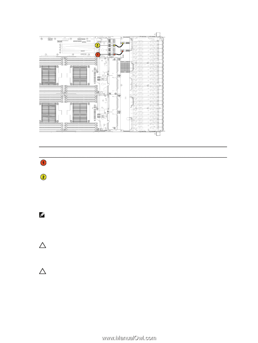
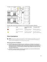
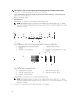
Figure 82. Cable routing−bottom middle plane to 2.5 inch hard drive for expander configuration Item Cable Hard-drive backplane cable From (bottom middle plane) Mini-SAS connector for system board 1 (J1) To (expander card) Mini-SAS connector ( 4~7) for system board 1 Hard-drive backplane cable Mini-SAS connector for Mini-SAS connector system board 3 (J3) (12~15) for system board 3 Direct backplanes NOTE: Following is the replacement procedure of SATA2 and SAS Direct Backplane for 3.5-inch hard drive systems. Replacement procedure for 2.5-inch of SATA2 and SAS Direct Backplane is similar to the Direct Backplane for 3.5-inch hard drive systems. Removing the direct backplane CAUTION: Many repairs may only be done by a certified service technician. You should only perform troubleshooting and simple repairs as authorized in your product documentation, or as directed by the online or telephone service and support team. Damage due to servicing that is not authorized by Dell is not covered by your warranty. Read and follow the safety instructions that came with the product. CAUTION: To prevent damage to the drives and backplane, you must remove the hard drives from the system before removing the backplane. 109
-
 1
1 -
2
-
3
-
4
-
5
-
6
-
7
-
8
-
9
-
10
-
11
-
12
-
13
-
14
-
15
-
16
-
17
-
18
-
19
-
20
-
21
-
22
-
23
-
24
-
25
-
26
-
27
-
28
-
29
-
30
-
31
-
32
-
33
-
34
-
35
-
36
-
37
-
38
-
39
-
40
-
41
-
42
-
43
-
44
-
45
-
46
-
47
-
48
-
49
-
50
-
51
-
52
-
53
-
54
-
55
-
56
-
57
-
58
-
59
-
60
-
61
-
62
-
63
-
64
-
65
-
66
-
67
-
68
-
69
-
70
-
71
-
72
-
73
-
74
-
75
-
76
-
77
-
78
-
79
-
80
-
81
-
82
-
83
-
84
-
85
-
86
-
87
-
88
-
89
-
90
-
91
-
92
-
93
-
94
-
95
-
96
-
97
-
98
-
99
-
100
-
101
-
102
-
103
-
 104
104 -
 105
105 -
 106
106 -
 107
107 -
 108
108 -
 109
109 -
 110
110 -
 111
111 -
 112
112 -
 113
113 -
 114
114 -
115
-
116
-
117
-
118
-
119
-
120
-
121
-
122
-
123
-
124
-
125
-
126
-
127
-
128
-
129
-
130
-
131
-
132
-
133
-
134
-
135
-
136
-
137
-
138
-
139
-
140
-
141
-
142
-
143
-
144
-
145
-
146
-
147
-
148
 |
 |