Dell PowerEdge C6300 Dell PowerEdge C6320 Owners Manual - Page 97
Installing a power distribution board, Cable routing for power distribution board, CAUTION: If removed
 |
View all Dell PowerEdge C6300 manuals
Add to My Manuals
Save this manual to your list of manuals |
Page 97 highlights
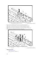
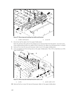
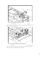
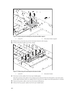
Installing a power distribution board CAUTION: Many repairs may only be done by a certified service technician. You should only perform troubleshooting and simple repairs as authorized in your product documentation, or as directed by the online or telephone service and support team. Damage due to servicing that is not authorized by Dell is not covered by your warranty. Read and follow the safety instructions that came with the product. CAUTION: If removed, you must replace the power distribution board 2 and the power distribution board-connector before replacing the power distribution board 1. 1. If removed, first place the power distribution board 2 in the system. Otherwise skip to step 5. NOTE: To install the power distribution board 2 below the power distribution board 1, angle the board during installation. 2. Replace the screws securing the power distribution board 2 to the system. 3. Replace the power distribution board-connector. 4. Connect all the cables to the power distribution board 2. You must route these cables properly through the tabs on the chassis to prevent them from being pinched or crimped. 5. Replace the power distribution board 1 to the system. 6. Replace the screws securing the power distribution board 1 to the system. 7. Connect all the cables to the power distribution board 1. You must route these cables properly through the tabs on the chassis to prevent them from being pinched or crimped. 8. Replace the power supply unit. 9. Close the system. 10. Reconnect the system to its electrical outlet and turn on the system, including any attached peripherals. Related Information Installing a power supply unit Closing the system Cable routing for power distribution board The following figures shows an example using a 1U node system. 97
-
 1
1 -
2
-
3
-
4
-
5
-
6
-
7
-
8
-
9
-
10
-
11
-
12
-
13
-
14
-
15
-
16
-
17
-
18
-
19
-
20
-
21
-
22
-
23
-
24
-
25
-
26
-
27
-
28
-
29
-
30
-
31
-
32
-
33
-
34
-
35
-
36
-
37
-
38
-
39
-
40
-
41
-
42
-
43
-
44
-
45
-
46
-
47
-
48
-
49
-
50
-
51
-
52
-
53
-
54
-
55
-
56
-
57
-
58
-
59
-
60
-
61
-
62
-
63
-
64
-
65
-
66
-
67
-
68
-
69
-
70
-
71
-
72
-
73
-
74
-
75
-
76
-
77
-
78
-
79
-
80
-
81
-
82
-
83
-
84
-
85
-
86
-
87
-
88
-
89
-
90
-
91
-
 92
92 -
 93
93 -
 94
94 -
 95
95 -
 96
96 -
 97
97 -
 98
98 -
 99
99 -
 100
100 -
 101
101 -
 102
102 -
103
-
104
-
105
-
106
-
107
-
108
-
109
-
110
-
111
-
112
-
113
-
114
-
115
-
116
-
117
-
118
-
119
-
120
-
121
-
122
-
123
-
124
-
125
-
126
-
127
-
128
-
129
-
130
-
131
-
132
-
133
-
134
-
135
-
136
-
137
-
138
-
139
-
140
-
141
-
142
-
143
-
144
-
145
-
146
-
147
-
148
 |
 |