Dell PowerEdge C6300 Dell PowerEdge C6320 Owners Manual - Page 137
Jumpers and connectors, C6320 system board connectors
 |
View all Dell PowerEdge C6300 manuals
Add to My Manuals
Save this manual to your list of manuals |
Page 137 highlights
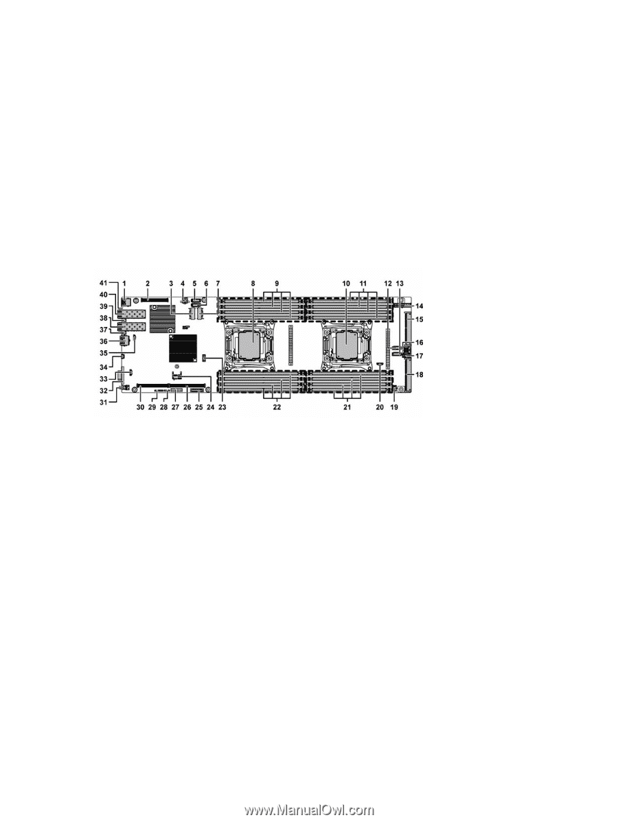
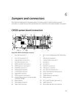
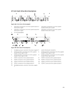
6 Jumpers and connectors This chapter provides specific information about the system jumpers. It also provides some basic information on jumpers and switches and describes the connectors on the various boards in the system. C6320 system board connectors Figure 102. C6320 system board connectors 1. rear USB Connector 1 3. mini-SAS Connector 0-3 5. onboard SATA Connector 4 7. mini-SAS Connector 6-9 9. DIMM sockets for processor 1 11. DIMM sockets for processor 2 13. SAS/SATA connector 4 15. middle plane connector 17. control panel connector 19. high power connector 21. DIMM sockets for processor 2 23. internal USB connector 2 (Left) and USB connector 3(Right) 25. system battery 27. CPLD debug connector 29. CPLD JTAG connector 2. PCI-E Gen3 x8 Mezzanine Slot 3 (Processor 1) 4. HDD Power Connector 6. onboard SATA Connector 5 8. processor 1 10. processor 2 12. SAS/SATA connector 5 14. main power connector 16. mini-SAS HD connector 0-3 18. PCI-E Gen3 x16 Slot 4 (Processor 2) 20. SGPIO connector 22. DIMM sockets for processor 1 24. TPM connector 26. PCI-E Gen3 x16 slot 1 (processor 1) 28. UART connector 30. PCI-E Gen3 x16 Slot 2 (processor 1) 137
-
 1
1 -
2
-
3
-
4
-
5
-
6
-
7
-
8
-
9
-
10
-
11
-
12
-
13
-
14
-
15
-
16
-
17
-
18
-
19
-
20
-
21
-
22
-
23
-
24
-
25
-
26
-
27
-
28
-
29
-
30
-
31
-
32
-
33
-
34
-
35
-
36
-
37
-
38
-
39
-
40
-
41
-
42
-
43
-
44
-
45
-
46
-
47
-
48
-
49
-
50
-
51
-
52
-
53
-
54
-
55
-
56
-
57
-
58
-
59
-
60
-
61
-
62
-
63
-
64
-
65
-
66
-
67
-
68
-
69
-
70
-
71
-
72
-
73
-
74
-
75
-
76
-
77
-
78
-
79
-
80
-
81
-
82
-
83
-
84
-
85
-
86
-
87
-
88
-
89
-
90
-
91
-
92
-
93
-
94
-
95
-
96
-
97
-
98
-
99
-
100
-
101
-
102
-
103
-
104
-
105
-
106
-
107
-
108
-
109
-
110
-
111
-
112
-
113
-
114
-
115
-
116
-
117
-
118
-
119
-
120
-
121
-
122
-
123
-
124
-
125
-
126
-
127
-
128
-
129
-
130
-
131
-
 132
132 -
 133
133 -
 134
134 -
 135
135 -
 136
136 -
 137
137 -
 138
138 -
 139
139 -
 140
140 -
 141
141 -
 142
142 -
143
-
144
-
145
-
146
-
147
-
148
 |
 |