Dell PowerEdge C6300 Dell PowerEdge C6320 Owners Manual - Page 19
Baseboard Management Controller (BMC) heart beat LED, Documentation matrix, Component, Indicator
 |
View all Dell PowerEdge C6300 manuals
Add to My Manuals
Save this manual to your list of manuals |
Page 19 highlights
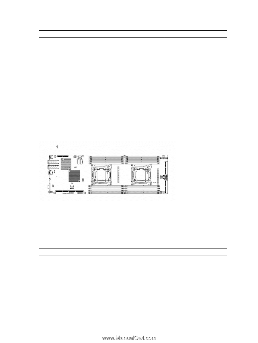
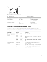
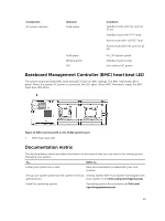
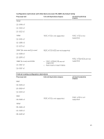
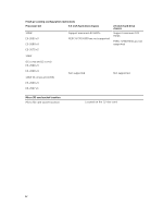
Component AC power indicator Indicator Solid amber Solid green Blinking green Off Condition Standby mode with Fan Lock for 15 sec Standby mode with OTP range Active mode with +12VDC Fault Active mode with Fan Lock for 15 sec DC_OK (power good) Standby mode normal Unit without AC power Baseboard Management Controller (BMC) heart beat LED The system board provides BMC heart beat LED (CR17) for BMC debugs. The BMC heart beat LED is green. When the system AC power is connected, the LED lights. When BMC firmware is ready, the BMC heart beat LED blinks. Figure 15. BMC heart beat LED on the C6320 system board 1. BMC heart beat LED Documentation matrix The documentation matrix provides information on documents that you can refer to for setting up and managing your system. To... Refer to... Install your system into a rack Rack documentation included with your rack solution Set up your system and know the system technical Getting Started With Your System that shipped with specifications your system or see Dell.com/poweredgemanuals Install the operating system Operating system documentation at Dell.com/ operatingsystemmanuals 19
-
 1
1 -
2
-
3
-
4
-
5
-
6
-
7
-
8
-
9
-
10
-
11
-
12
-
13
-
 14
14 -
 15
15 -
 16
16 -
 17
17 -
 18
18 -
 19
19 -
 20
20 -
 21
21 -
 22
22 -
 23
23 -
 24
24 -
25
-
26
-
27
-
28
-
29
-
30
-
31
-
32
-
33
-
34
-
35
-
36
-
37
-
38
-
39
-
40
-
41
-
42
-
43
-
44
-
45
-
46
-
47
-
48
-
49
-
50
-
51
-
52
-
53
-
54
-
55
-
56
-
57
-
58
-
59
-
60
-
61
-
62
-
63
-
64
-
65
-
66
-
67
-
68
-
69
-
70
-
71
-
72
-
73
-
74
-
75
-
76
-
77
-
78
-
79
-
80
-
81
-
82
-
83
-
84
-
85
-
86
-
87
-
88
-
89
-
90
-
91
-
92
-
93
-
94
-
95
-
96
-
97
-
98
-
99
-
100
-
101
-
102
-
103
-
104
-
105
-
106
-
107
-
108
-
109
-
110
-
111
-
112
-
113
-
114
-
115
-
116
-
117
-
118
-
119
-
120
-
121
-
122
-
123
-
124
-
125
-
126
-
127
-
128
-
129
-
130
-
131
-
132
-
133
-
134
-
135
-
136
-
137
-
138
-
139
-
140
-
141
-
142
-
143
-
144
-
145
-
146
-
147
-
148
 |
 |