Dell Poweredge C4130 Dell Owners Manual - Page 10
Event and Error Messages Reference Guide at, Indicator, button, or, connector, Description
 |
View all Dell Poweredge C4130 manuals
Add to My Manuals
Save this manual to your list of manuals |
Page 10 highlights
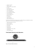
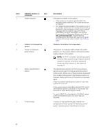
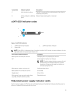
Item 1 Indicator, button, or connector Health indicator Icon 2 Ambient air temperature sensor 3 Power-on indicator, power button 4 System identification button 5 Control panel Description Indicates the health of the system. • If the system is on and in good health, the indicator lights solid blue. No corrective action is required. • The indicator blinks amber if the system is on or in standby, and if any error exists (for example, a failed fan). See the System Event Log or system messages for the specific issue. For more information on error messages, see the Dell Event and Error Messages Reference Guide at dell.com/esmmanuals. Invalid memory configurations can cause the system to halt at startup without any video output. See Getting help. Measures the ambient air temperature. The power-on indicator lights when the system power is on. The power button controls the power supply output to the system. NOTE: On ACPI-compliant operating systems, turning off the system using the power button causes the system to perform a graceful shutdown before power to the system is turned off. The identification button on the front and back panels can be used to locate a particular system within a rack. When one of these buttons is pressed, the corresponding system identification button on the back flashes until one of the buttons is pressed again. Press the system identification button to turn the system ID on or off. If the system stops responding during POST, press and hold the system ID button for more than five seconds to enter BIOS progress mode. To reset iDRAC (if not disabled in F2 iDRAC setup), press and hold the button for more than 15 seconds. Consists of the health indicator, ambient air temperature sensor, power-on indicator, power button, and the system identification button. 10
-
 1
1 -
2
-
3
-
4
-
 5
5 -
 6
6 -
 7
7 -
 8
8 -
 9
9 -
 10
10 -
 11
11 -
 12
12 -
 13
13 -
 14
14 -
 15
15 -
16
-
17
-
18
-
19
-
20
-
21
-
22
-
23
-
24
-
25
-
26
-
27
-
28
-
29
-
30
-
31
-
32
-
33
-
34
-
35
-
36
-
37
-
38
-
39
-
40
-
41
-
42
-
43
-
44
-
45
-
46
-
47
-
48
-
49
-
50
-
51
-
52
-
53
-
54
-
55
-
56
-
57
-
58
-
59
-
60
-
61
-
62
-
63
-
64
-
65
-
66
-
67
-
68
-
69
-
70
-
71
-
72
-
73
-
74
-
75
-
76
-
77
-
78
-
79
-
80
-
81
-
82
-
83
-
84
-
85
-
86
-
87
-
88
-
89
-
90
-
91
-
92
-
93
-
94
-
95
-
96
-
97
-
98
-
99
-
100
-
101
-
102
-
103
-
104
-
105
-
106
-
107
-
108
-
109
-
110
-
111
-
112
-
113
-
114
-
115
-
116
-
117
-
118
-
119
-
120
-
121
-
122
-
123
-
124
-
125
-
126
-
127
-
128
-
129
-
130
-
131
-
132
-
133
-
134
-
135
-
136
-
137
-
138
-
139
-
140
-
141
-
142
-
143
-
144
-
145
-
146
-
147
-
148
-
149
-
150
-
151
-
152
-
153
-
154
-
155
-
156
-
157
-
158
-
159
-
160
-
161
-
162
-
163
 |
 |
