Dell Poweredge C4130 Dell Owners Manual - Page 12
NIC indicator codes, Indicator, button, or, connector, Description, Convention, Indicator pattern
 |
View all Dell Poweredge C4130 manuals
Add to My Manuals
Save this manual to your list of manuals |
Page 12 highlights
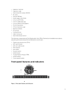
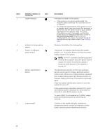
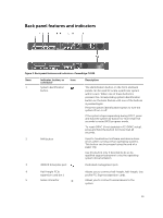
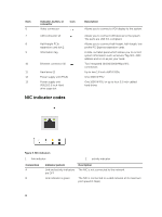
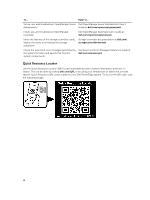
Item 6 7 8 9 Indicator, button, or connector Video connector USB connector (2) Icon Half-height PCIe expansion card slot 2 Information tag 10 Ethernet connector (2) 11 Hard drive (2) 12 Power supply unit (PSU1) 13 Power supply unit (PSU2)/2.5 inch Hard drive cage slot NIC indicator codes Description Allows you to connect a VGA display to the system. Allows you to connect USB devices to the system. The ports are USB 3.0-compliant. Allows you to connect half-height, half-length, low profile PCI Express expansion cards. A slide-out label panel which allows you to record system information such as Service Tag, NIC, MAC address and so on as per your need. Two integrated 10/100/1000/Mbps NIC connectors. Up to two 1.8 inch uSATA SSDs. One 1600 W PSU. One 1600 W PSU or up to four 2.5 inch cabled hard drives. Figure 3. NIC indicators 1. link indicator 2. activity indicator Convention A B Indicator pattern Link and activity indicators are OFF Link indicator is green Description The NIC is not connected to the network. The NIC is connected to a valid network at its maximum port speed (1 Gbps). 12
-
 1
1 -
2
-
3
-
4
-
5
-
6
-
 7
7 -
 8
8 -
 9
9 -
 10
10 -
 11
11 -
 12
12 -
 13
13 -
 14
14 -
 15
15 -
 16
16 -
 17
17 -
18
-
19
-
20
-
21
-
22
-
23
-
24
-
25
-
26
-
27
-
28
-
29
-
30
-
31
-
32
-
33
-
34
-
35
-
36
-
37
-
38
-
39
-
40
-
41
-
42
-
43
-
44
-
45
-
46
-
47
-
48
-
49
-
50
-
51
-
52
-
53
-
54
-
55
-
56
-
57
-
58
-
59
-
60
-
61
-
62
-
63
-
64
-
65
-
66
-
67
-
68
-
69
-
70
-
71
-
72
-
73
-
74
-
75
-
76
-
77
-
78
-
79
-
80
-
81
-
82
-
83
-
84
-
85
-
86
-
87
-
88
-
89
-
90
-
91
-
92
-
93
-
94
-
95
-
96
-
97
-
98
-
99
-
100
-
101
-
102
-
103
-
104
-
105
-
106
-
107
-
108
-
109
-
110
-
111
-
112
-
113
-
114
-
115
-
116
-
117
-
118
-
119
-
120
-
121
-
122
-
123
-
124
-
125
-
126
-
127
-
128
-
129
-
130
-
131
-
132
-
133
-
134
-
135
-
136
-
137
-
138
-
139
-
140
-
141
-
142
-
143
-
144
-
145
-
146
-
147
-
148
-
149
-
150
-
151
-
152
-
153
-
154
-
155
-
156
-
157
-
158
-
159
-
160
-
161
-
162
-
163
 |
 |
