Dell Poweredge C4130 Dell Owners Manual - Page 77
Expansion card cabling diagrams, Cabling two expansion cards
 |
View all Dell Poweredge C4130 manuals
Add to My Manuals
Save this manual to your list of manuals |
Page 77 highlights
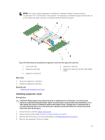
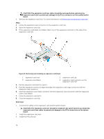
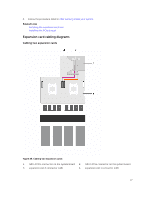
4. Follow the procedure listed in After working inside your system. Related Links Installing the expansion card riser Installing the PCIe shroud Expansion card cabling diagrams Cabling two expansion cards Figure 26. Cabling two expansion cards 1. GPU 4 PCIe connector on the system board 2. GPU 1 PCIe connector on the system board 3. expansion slot 2 connector (x16) 4. expansion slot 1 connector (x16) 77
-
 1
1 -
2
-
3
-
4
-
5
-
6
-
7
-
8
-
9
-
10
-
11
-
12
-
13
-
14
-
15
-
16
-
17
-
18
-
19
-
20
-
21
-
22
-
23
-
24
-
25
-
26
-
27
-
28
-
29
-
30
-
31
-
32
-
33
-
34
-
35
-
36
-
37
-
38
-
39
-
40
-
41
-
42
-
43
-
44
-
45
-
46
-
47
-
48
-
49
-
50
-
51
-
52
-
53
-
54
-
55
-
56
-
57
-
58
-
59
-
60
-
61
-
62
-
63
-
64
-
65
-
66
-
67
-
68
-
69
-
70
-
71
-
 72
72 -
 73
73 -
 74
74 -
 75
75 -
 76
76 -
 77
77 -
 78
78 -
 79
79 -
 80
80 -
 81
81 -
 82
82 -
83
-
84
-
85
-
86
-
87
-
88
-
89
-
90
-
91
-
92
-
93
-
94
-
95
-
96
-
97
-
98
-
99
-
100
-
101
-
102
-
103
-
104
-
105
-
106
-
107
-
108
-
109
-
110
-
111
-
112
-
113
-
114
-
115
-
116
-
117
-
118
-
119
-
120
-
121
-
122
-
123
-
124
-
125
-
126
-
127
-
128
-
129
-
130
-
131
-
132
-
133
-
134
-
135
-
136
-
137
-
138
-
139
-
140
-
141
-
142
-
143
-
144
-
145
-
146
-
147
-
148
-
149
-
150
-
151
-
152
-
153
-
154
-
155
-
156
-
157
-
158
-
159
-
160
-
161
-
162
-
163
 |
 |

4.
Follow the procedure listed in
After working inside your system
.
Related Links
Installing the expansion card riser
Installing the PCIe shroud
Expansion card cabling diagrams
Cabling two expansion cards
Figure 26. Cabling two expansion cards
1.
GPU 4 PCIe connector on the system board
2.
GPU 1 PCIe connector on the system board
3.
expansion slot 2 connector (x16)
4.
expansion slot 1 connector (x16)
77