Dell Poweredge C4130 Dell Owners Manual - Page 72
Removing the expansion card riser, Configuration A, B, C, and D
 |
View all Dell Poweredge C4130 manuals
Add to My Manuals
Save this manual to your list of manuals |
Page 72 highlights
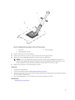
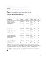
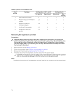
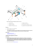
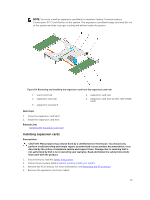
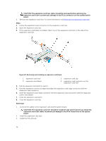
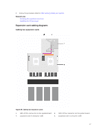
Table 5. Expansion card installation order Card priority Card type Configuration A, B, C, and D Slot priority Max allowed 1 RAID H330 (low profile) 1 1 2 Mellanox dual port InfiniBand 1, 2 2 adapter 3 Mellanox single port InfiniBand adapter 1, 2 2 3 10 Gb NICs (low profile) 1, 2 2 4 10 Gb SFP+ NICs (low 1, 2 2 profile) Configuration E Slot priority Max allowed 1 1 1 1 1 1 1 1 1 1 Removing the expansion card riser Prerequisites CAUTION: Many repairs may only be done by a certified service technician. You should only perform troubleshooting and simple repairs as authorized in your product documentation, or as directed by the online or telephone service and support team. Damage due to servicing that is not authorized by Dell is not covered by your warranty. Read and follow the safety instructions that came with the product. 1. Ensure that you read the Safety instructions. 2. Follow the procedure listed in Before working inside your system. 3. Remove the PCIe shroud. See Removing the PCIe shroud. 4. If installed, disconnect the expansion card riser cables from the system board. CAUTION: The expansion card riser cables must be removed before removing the expansion card riser to prevent pin damage in the PCIe connectors on the system board. Steps Holding the touch points, lift the expansion card riser from the riser connector on the system board. 72
-
 1
1 -
2
-
3
-
4
-
5
-
6
-
7
-
8
-
9
-
10
-
11
-
12
-
13
-
14
-
15
-
16
-
17
-
18
-
19
-
20
-
21
-
22
-
23
-
24
-
25
-
26
-
27
-
28
-
29
-
30
-
31
-
32
-
33
-
34
-
35
-
36
-
37
-
38
-
39
-
40
-
41
-
42
-
43
-
44
-
45
-
46
-
47
-
48
-
49
-
50
-
51
-
52
-
53
-
54
-
55
-
56
-
57
-
58
-
59
-
60
-
61
-
62
-
63
-
64
-
65
-
66
-
 67
67 -
 68
68 -
 69
69 -
 70
70 -
 71
71 -
 72
72 -
 73
73 -
 74
74 -
 75
75 -
 76
76 -
 77
77 -
78
-
79
-
80
-
81
-
82
-
83
-
84
-
85
-
86
-
87
-
88
-
89
-
90
-
91
-
92
-
93
-
94
-
95
-
96
-
97
-
98
-
99
-
100
-
101
-
102
-
103
-
104
-
105
-
106
-
107
-
108
-
109
-
110
-
111
-
112
-
113
-
114
-
115
-
116
-
117
-
118
-
119
-
120
-
121
-
122
-
123
-
124
-
125
-
126
-
127
-
128
-
129
-
130
-
131
-
132
-
133
-
134
-
135
-
136
-
137
-
138
-
139
-
140
-
141
-
142
-
143
-
144
-
145
-
146
-
147
-
148
-
149
-
150
-
151
-
152
-
153
-
154
-
155
-
156
-
157
-
158
-
159
-
160
-
161
-
162
-
163
 |
 |
