Dell Poweredge C4130 Dell Owners Manual - Page 102
Installing the cable routing clip, System board, Removing the system board
 |
View all Dell Poweredge C4130 manuals
Add to My Manuals
Save this manual to your list of manuals |
Page 102 highlights
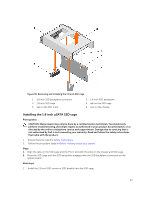
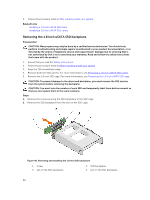
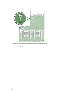
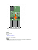
Installing the cable routing clip Prerequisites CAUTION: Many repairs may only be done by a certified service technician. You should only perform troubleshooting and simple repairs as authorized in your product documentation, or as directed by the online or telephone service and support team. Damage due to servicing that is not authorized by Dell is not covered by your warranty. Read and follow the safety instructions that came with the product. 1. Ensure that you read the Safety instructions. 2. Follow the procedure listed in Before working inside your system. Steps 1. Align the screw holes on the cable routing clip with the screw holes on the system board and lower the clip on the system board. 2. Secure the cable routing clip to the system board by using the screws. Next steps 1. Connect and route the cables through the cable routing clip. 2. Follow the procedure listed in After working inside your system. System board Removing the system board Prerequisites NOTE: This is a Field Replaceable Unit (FRU). Removal and installation procedures should be performed only by Dell certified service technicians. CAUTION: Many repairs may only be done by a certified service technician. You should only perform troubleshooting and simple repairs as authorized in your product documentation, or as directed by the online or telephone service and support team. Damage due to servicing that is not authorized by Dell is not covered by your warranty. Read and follow the safety instructions that came with the product. CAUTION: If you are using the Trusted Platform Module (TPM) with an encryption key, you may be prompted to create a recovery key during program or System Setup. Be sure to create and safely store this recovery key. If you replace this system board, you must supply the recovery key when you restart your system or program before you can access the encrypted data on your hard drives. CAUTION: Do not attempt to remove the Trusted Platform Module (TPM) from the system board. Once the TPM is installed, it is cryptographically bound to that specific system board. Any attempt to remove an installed TPM breaks the cryptographic binding, and it cannot be reinstalled or installed on another system board. 1. Ensure that you read the Safety instructions. 2. Follow the procedure listed in Before working inside your system. 3. Keep the Philips #2 screwdriver ready. 4. Remove the following components: a. PCIe shroud. See Removing the PCIe shroud 102
-
 1
1 -
2
-
3
-
4
-
5
-
6
-
7
-
8
-
9
-
10
-
11
-
12
-
13
-
14
-
15
-
16
-
17
-
18
-
19
-
20
-
21
-
22
-
23
-
24
-
25
-
26
-
27
-
28
-
29
-
30
-
31
-
32
-
33
-
34
-
35
-
36
-
37
-
38
-
39
-
40
-
41
-
42
-
43
-
44
-
45
-
46
-
47
-
48
-
49
-
50
-
51
-
52
-
53
-
54
-
55
-
56
-
57
-
58
-
59
-
60
-
61
-
62
-
63
-
64
-
65
-
66
-
67
-
68
-
69
-
70
-
71
-
72
-
73
-
74
-
75
-
76
-
77
-
78
-
79
-
80
-
81
-
82
-
83
-
84
-
85
-
86
-
87
-
88
-
89
-
90
-
91
-
92
-
93
-
94
-
95
-
96
-
 97
97 -
 98
98 -
 99
99 -
 100
100 -
 101
101 -
 102
102 -
 103
103 -
 104
104 -
 105
105 -
 106
106 -
 107
107 -
108
-
109
-
110
-
111
-
112
-
113
-
114
-
115
-
116
-
117
-
118
-
119
-
120
-
121
-
122
-
123
-
124
-
125
-
126
-
127
-
128
-
129
-
130
-
131
-
132
-
133
-
134
-
135
-
136
-
137
-
138
-
139
-
140
-
141
-
142
-
143
-
144
-
145
-
146
-
147
-
148
-
149
-
150
-
151
-
152
-
153
-
154
-
155
-
156
-
157
-
158
-
159
-
160
-
161
-
162
-
163
 |
 |
