Dell Poweredge C4130 Dell Owners Manual - Page 71
Expansion card riser and expansion cards, Expansion card installation guidelines
 |
View all Dell Poweredge C4130 manuals
Add to My Manuals
Save this manual to your list of manuals |
Page 71 highlights
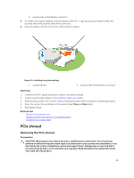
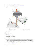
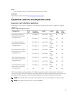
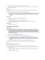
Steps Insert the tabs on the PCIe shroud into the slots on the heat sink. Next steps Follow the procedure listed in After working inside your system. Expansion card riser and expansion cards Expansion card installation guidelines Depending on your system configuration, the following PCI Express generation 3 expansion cards are supported: Table 4. Supported expansion cards Configuration Four GPUs with switch board and one processor (Configuration A) PCIe slot 1 2 Processor connection Processor 1 Processor 1 Four GPUs with switch 1 board and two processors (Configuration B) 2 Processor 1 Processor 1 Height Length Low Profile Low Profile Low Profile Low Profile Half Length Half Length Half Length Half Length Link width x8 x16 x8 x16 Slot width x16 x16 x16 x16 Four GPUs without switch 1 board and two processors (Configuration C) 2 Processor 1 Low Profile Half x8 x16 Length Processor 2 Low Profile Half x8 x16 Length Two GPUs without switch 1 board and two processors (Configuration D) 2 Processor 1 Low Profile Half x16 x16 Length Processor 2 Low Profile Half x16 x16 Length Two GPUs without switch 1 board and one processor (Configuration E) 2 Processor 1 Low Profile Half x8 x16 Length NA NA NA NA NA The following table provides guidelines for installing expansion cards to ensure proper cooling and mechanical fit. The expansion cards with the highest priority should be installed first using the slot priority indicated. All other expansion cards should be installed in the card priority and slot priority order. NOTE: The x16 link width riser cards on the expansion card riser are cabled to the system board. NOTE: The expansion card slots are not hot swappable. 71
-
 1
1 -
2
-
3
-
4
-
5
-
6
-
7
-
8
-
9
-
10
-
11
-
12
-
13
-
14
-
15
-
16
-
17
-
18
-
19
-
20
-
21
-
22
-
23
-
24
-
25
-
26
-
27
-
28
-
29
-
30
-
31
-
32
-
33
-
34
-
35
-
36
-
37
-
38
-
39
-
40
-
41
-
42
-
43
-
44
-
45
-
46
-
47
-
48
-
49
-
50
-
51
-
52
-
53
-
54
-
55
-
56
-
57
-
58
-
59
-
60
-
61
-
62
-
63
-
64
-
65
-
 66
66 -
 67
67 -
 68
68 -
 69
69 -
 70
70 -
 71
71 -
 72
72 -
 73
73 -
 74
74 -
 75
75 -
 76
76 -
77
-
78
-
79
-
80
-
81
-
82
-
83
-
84
-
85
-
86
-
87
-
88
-
89
-
90
-
91
-
92
-
93
-
94
-
95
-
96
-
97
-
98
-
99
-
100
-
101
-
102
-
103
-
104
-
105
-
106
-
107
-
108
-
109
-
110
-
111
-
112
-
113
-
114
-
115
-
116
-
117
-
118
-
119
-
120
-
121
-
122
-
123
-
124
-
125
-
126
-
127
-
128
-
129
-
130
-
131
-
132
-
133
-
134
-
135
-
136
-
137
-
138
-
139
-
140
-
141
-
142
-
143
-
144
-
145
-
146
-
147
-
148
-
149
-
150
-
151
-
152
-
153
-
154
-
155
-
156
-
157
-
158
-
159
-
160
-
161
-
162
-
163
 |
 |
