Dell Poweredge C4130 Dell Owners Manual - Page 136
Control panel module, Removing the control panel module
 |
View all Dell Poweredge C4130 manuals
Add to My Manuals
Save this manual to your list of manuals |
Page 136 highlights
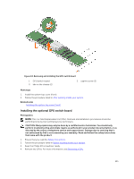
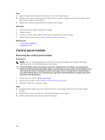
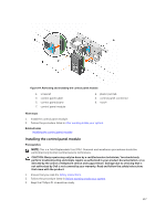
Steps 1. Align the tabs on the chassis with the slots on the GPU switch board. 2. Slide the GPU switch board toward the back of the chassis to engage the slots on the GPU switch board with the tabs on the chassis. 3. Tighten the screws securing the switch board to the chassis. Next steps 1. Connect the GPU switch board power cable. 2. Install the GPUs. 3. Connect the GPU signal cables to the switch board and the system board. 4. Follow the procedure listed in After working inside your system. Related Links GPU cabling diagrams Installing a GPU Control panel module Removing the control panel module Prerequisites NOTE: This is a Field Replaceable Unit (FRU). Removal and installation procedures should be performed only by Dell certified service technicians. CAUTION: Many repairs may only be done by a certified service technician. You should only perform troubleshooting and simple repairs as authorized in your product documentation, or as directed by the online or telephone service and support team. Damage due to servicing that is not authorized by Dell is not covered by your warranty. Read and follow the safety instructions that came with the product. 1. Ensure that you read the Safety instructions. 2. Follow the procedure listed in Before working inside your system. 3. Keep the Phillips #1 screwdriver ready. Steps 1. Hold and pull the plastic pull tab to disconnect the control panel cable from the control panel module. 2. Remove the screws securing the control panel module to the chassis. 3. Lift the control panel module away from the chassis. 136
-
 1
1 -
2
-
3
-
4
-
5
-
6
-
7
-
8
-
9
-
10
-
11
-
12
-
13
-
14
-
15
-
16
-
17
-
18
-
19
-
20
-
21
-
22
-
23
-
24
-
25
-
26
-
27
-
28
-
29
-
30
-
31
-
32
-
33
-
34
-
35
-
36
-
37
-
38
-
39
-
40
-
41
-
42
-
43
-
44
-
45
-
46
-
47
-
48
-
49
-
50
-
51
-
52
-
53
-
54
-
55
-
56
-
57
-
58
-
59
-
60
-
61
-
62
-
63
-
64
-
65
-
66
-
67
-
68
-
69
-
70
-
71
-
72
-
73
-
74
-
75
-
76
-
77
-
78
-
79
-
80
-
81
-
82
-
83
-
84
-
85
-
86
-
87
-
88
-
89
-
90
-
91
-
92
-
93
-
94
-
95
-
96
-
97
-
98
-
99
-
100
-
101
-
102
-
103
-
104
-
105
-
106
-
107
-
108
-
109
-
110
-
111
-
112
-
113
-
114
-
115
-
116
-
117
-
118
-
119
-
120
-
121
-
122
-
123
-
124
-
125
-
126
-
127
-
128
-
129
-
130
-
 131
131 -
 132
132 -
 133
133 -
 134
134 -
 135
135 -
 136
136 -
 137
137 -
 138
138 -
 139
139 -
 140
140 -
 141
141 -
142
-
143
-
144
-
145
-
146
-
147
-
148
-
149
-
150
-
151
-
152
-
153
-
154
-
155
-
156
-
157
-
158
-
159
-
160
-
161
-
162
-
163
 |
 |
