Dell Poweredge C4130 Dell Owners Manual - Page 9
Front panel features and indicators, Internal dual SD module IDSDM
 |
View all Dell Poweredge C4130 manuals
Add to My Manuals
Save this manual to your list of manuals |
Page 9 highlights
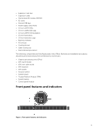
• Expansion card riser • Expansion cards • Internal dual SD module (IDSDM) • SD cards • Internal USB keys • Power supply units (PSUs) • 1.8 inch uSATA SSDs • 1.8 inch uSATA SSD cage • 1.8 inch uSATA SSD backplane • 2.5 inch hard drives • 2.5 inch hard drive cage • Memory modules • PCI shroud • Cooling shroud • Cable routing clip • Heat sinks and processors The following components are Field Replaceable Units (FRUs). Removal and installation procedures should be performed only by Dell certified service technicians. • Graphics processing units (GPUs) • GPU switch board • GPU riser cable board • GPU brackets • GPU blanks • Intrusion switch • System board • Trusted Platform Module (TPM) • System battery • Control panel module Front panel features and indicators Figure 1. Front panel features and indicators 9
-
 1
1 -
2
-
3
-
 4
4 -
 5
5 -
 6
6 -
 7
7 -
 8
8 -
 9
9 -
 10
10 -
 11
11 -
 12
12 -
 13
13 -
 14
14 -
15
-
16
-
17
-
18
-
19
-
20
-
21
-
22
-
23
-
24
-
25
-
26
-
27
-
28
-
29
-
30
-
31
-
32
-
33
-
34
-
35
-
36
-
37
-
38
-
39
-
40
-
41
-
42
-
43
-
44
-
45
-
46
-
47
-
48
-
49
-
50
-
51
-
52
-
53
-
54
-
55
-
56
-
57
-
58
-
59
-
60
-
61
-
62
-
63
-
64
-
65
-
66
-
67
-
68
-
69
-
70
-
71
-
72
-
73
-
74
-
75
-
76
-
77
-
78
-
79
-
80
-
81
-
82
-
83
-
84
-
85
-
86
-
87
-
88
-
89
-
90
-
91
-
92
-
93
-
94
-
95
-
96
-
97
-
98
-
99
-
100
-
101
-
102
-
103
-
104
-
105
-
106
-
107
-
108
-
109
-
110
-
111
-
112
-
113
-
114
-
115
-
116
-
117
-
118
-
119
-
120
-
121
-
122
-
123
-
124
-
125
-
126
-
127
-
128
-
129
-
130
-
131
-
132
-
133
-
134
-
135
-
136
-
137
-
138
-
139
-
140
-
141
-
142
-
143
-
144
-
145
-
146
-
147
-
148
-
149
-
150
-
151
-
152
-
153
-
154
-
155
-
156
-
157
-
158
-
159
-
160
-
161
-
162
-
163
 |
 |
