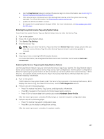
Dell Poweredge C4130 Dell Owners Manual - Page 106
If applicable, install the Trusted Platform Module TPM., Cooling shroud. See
 |
View all Dell Poweredge C4130 manuals
Add to My Manuals
Save this manual to your list of manuals |
Page 106 highlights
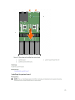
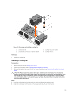
CAUTION: Many repairs may only be done by a certified service technician. You should only perform troubleshooting and simple repairs as authorized in your product documentation, or as directed by the online or telephone service and support team. Damage due to servicing that is not authorized by Dell is not covered by your warranty. Read and follow the safety instructions that came with the product. 1. Ensure that you read the Safety instructions. 2. Follow the procedure listed in Before working inside your system. 3. Keep the Phillips #2 screwdriver ready. Steps 1. Unpack the new system board. CAUTION: Do not lift the system board by holding a memory module, processor, or other components. CAUTION: Take care not to damage the system identification button while placing the system board into the chassis. 2. Hold the system board holders and lower the system board into the chassis at an angle so that the connectors on the back of the system board engage with the slots on the back of the chassis. 3. Push the system board toward the back of the chassis until the board is firmly seated. 4. Secure the system board to the chassis by using the screws. Next steps 1. If applicable, install the Trusted Platform Module (TPM). For information on installing the TPM, see Installing the Trusted Platform Module. For more information on TPM, see Trusted Platform Module. 2. Replace the following components: a. Internal USB key, if applicable. See Replacing the internal USB key b. Internal dual SD module. See Installing the internal dual SD module c. Expansion card riser. See Installing the expansion card riser d. PSU(s). See Installing an AC power supply unit e. 2.5 inch hard drive cage, if applicable. See Installing the optional 2.5 inch hard drive cage f. Processors(s)/processor blank(s). See Installing a processor, Installing a processor blank g. Heat sink(s). See Installing a heat sink h. PCIe shroud. See Installing the PCIe shroud i. Memory modules and memory module blanks. See Installing memory modules j. 1.8 inch SSD cage with the backplane. See Installing the 1.8 inch uSATA SSD cage, Installing the 1.8 inch uSATA SSD backplane k. Cooling shroud. See Installing the cooling shroud l. Cable routing clip. See Installing the cable routing clip 3. Reconnect all cables to the system board. NOTE: Ensure that the cables inside the system are routed along the chassis wall and the GPU and hard drive cables are routed through the cable routing clip. 4. Follow the procedure listed in After working inside your system. 5. Ensure that you perform the following steps: 106
-
 1
1 -
2
-
3
-
4
-
5
-
6
-
7
-
8
-
9
-
10
-
11
-
12
-
13
-
14
-
15
-
16
-
17
-
18
-
19
-
20
-
21
-
22
-
23
-
24
-
25
-
26
-
27
-
28
-
29
-
30
-
31
-
32
-
33
-
34
-
35
-
36
-
37
-
38
-
39
-
40
-
41
-
42
-
43
-
44
-
45
-
46
-
47
-
48
-
49
-
50
-
51
-
52
-
53
-
54
-
55
-
56
-
57
-
58
-
59
-
60
-
61
-
62
-
63
-
64
-
65
-
66
-
67
-
68
-
69
-
70
-
71
-
72
-
73
-
74
-
75
-
76
-
77
-
78
-
79
-
80
-
81
-
82
-
83
-
84
-
85
-
86
-
87
-
88
-
89
-
90
-
91
-
92
-
93
-
94
-
95
-
96
-
97
-
98
-
99
-
100
-
 101
101 -
 102
102 -
 103
103 -
 104
104 -
 105
105 -
 106
106 -
 107
107 -
 108
108 -
 109
109 -
 110
110 -
 111
111 -
112
-
113
-
114
-
115
-
116
-
117
-
118
-
119
-
120
-
121
-
122
-
123
-
124
-
125
-
126
-
127
-
128
-
129
-
130
-
131
-
132
-
133
-
134
-
135
-
136
-
137
-
138
-
139
-
140
-
141
-
142
-
143
-
144
-
145
-
146
-
147
-
148
-
149
-
150
-
151
-
152
-
153
-
154
-
155
-
156
-
157
-
158
-
159
-
160
-
161
-
162
-
163
 |
 |
