Dell Poweredge C4130 Dell Owners Manual - Page 103
Internal dual SD module. See, Heat sinks. See
 |
View all Dell Poweredge C4130 manuals
Add to My Manuals
Save this manual to your list of manuals |
Page 103 highlights
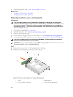
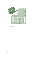
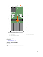
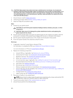
b. Expansion card riser. See Removing the expansion card riser c. PSU(s). See Removing an AC power supply unit d. 2.5 inch hard drive cage, if applicable. See Removing the optional 2.5 inch hard drive cage e. Internal dual SD module. See Removing the internal dual SD module f. 1.8 inch SSD cage with backplane. See Removing the 1.8 inch uSATA SSD cage, Removing the 1.8 inch uSATA SSD backplane g. Internal USB key (if installed). See Replacing the internal USB key h. Cooling shroud. See Removing the cooling shroud i. Heat sink(s). See Removing a heat sink j. Processor(s)/processor blank. See Removing a processor, Removing a processor blank CAUTION: To prevent damage to the processor pins when replacing a faulty system board, ensure that you cover the processor socket with the processor protective cap. k. Memory modules and memory module blanks. See Removing memory modules l. Cable routing clip. See Removing the cable routing clip 5. Disconnect all cables from the system board. Steps 1. Remove the screws that secure the system board to the chassis. CAUTION: Take care not to damage the system identification button while removing the system board from the chassis. CAUTION: Do not lift the system board by holding a memory module, processor, or other components. 2. Lift the system board by holding both the system board holders, and slide the system board toward the front of the chassis. The connectors are disengaged from the back of the chassis slots. 3. Lift the system board out of the chassis. 103
-
 1
1 -
2
-
3
-
4
-
5
-
6
-
7
-
8
-
9
-
10
-
11
-
12
-
13
-
14
-
15
-
16
-
17
-
18
-
19
-
20
-
21
-
22
-
23
-
24
-
25
-
26
-
27
-
28
-
29
-
30
-
31
-
32
-
33
-
34
-
35
-
36
-
37
-
38
-
39
-
40
-
41
-
42
-
43
-
44
-
45
-
46
-
47
-
48
-
49
-
50
-
51
-
52
-
53
-
54
-
55
-
56
-
57
-
58
-
59
-
60
-
61
-
62
-
63
-
64
-
65
-
66
-
67
-
68
-
69
-
70
-
71
-
72
-
73
-
74
-
75
-
76
-
77
-
78
-
79
-
80
-
81
-
82
-
83
-
84
-
85
-
86
-
87
-
88
-
89
-
90
-
91
-
92
-
93
-
94
-
95
-
96
-
97
-
 98
98 -
 99
99 -
 100
100 -
 101
101 -
 102
102 -
 103
103 -
 104
104 -
 105
105 -
 106
106 -
 107
107 -
 108
108 -
109
-
110
-
111
-
112
-
113
-
114
-
115
-
116
-
117
-
118
-
119
-
120
-
121
-
122
-
123
-
124
-
125
-
126
-
127
-
128
-
129
-
130
-
131
-
132
-
133
-
134
-
135
-
136
-
137
-
138
-
139
-
140
-
141
-
142
-
143
-
144
-
145
-
146
-
147
-
148
-
149
-
150
-
151
-
152
-
153
-
154
-
155
-
156
-
157
-
158
-
159
-
160
-
161
-
162
-
163
 |
 |
