HP Armada 1100 Armada 1100 Family of Personal Computers Maintenance and Servic - Page 106
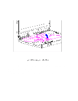
The System Board, screws to the heatspreader.
 |
View all HP Armada 1100 manuals
Add to My Manuals
Save this manual to your list of manuals |
Page 106 highlights
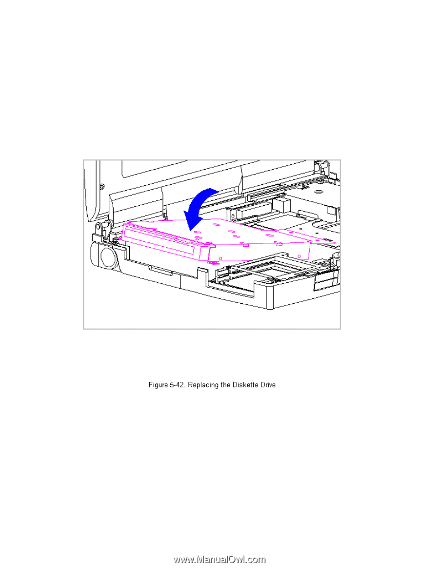
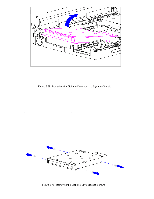
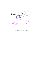
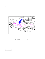
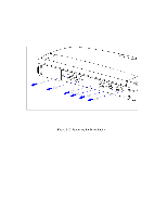
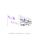
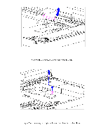
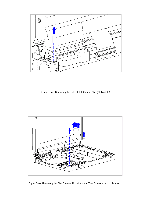
1. Replace the diskette drive into the diskette drive bracket. Use the four screws to secure the diskette drive to the bracket. NOTE: When replacing the diskette drive into the bracket, secure the front two screws first. 2. Toe in the back end of the diskette drive into the system chassis. IMPORTANT: Ensure that the diskette drive door does not catch on the outside edge of the system unit module. 3. Close the diskette drive door slightly while lowering the front of the diskette drive into the system chassis (Figure 5-42). 4. Reconnect the diskette drive cable and reinstall the five screws. IMPORTANT: The screw order for the five screws is important. The three screws that connect the diskette drive bracket to the system board have a tighter tolerance than the two screws that connect the bracket to the heatspreader; therefore, you must install the three screws to the system board before you install the two screws to the heatspreader. The System Board To remove the system board, follow these steps: 1. Turn the computer off and remove all external devices, including the battery pack and the AC Adapter. Remove the diskette and PC Card, if
-
 1
1 -
2
-
3
-
4
-
5
-
6
-
7
-
8
-
9
-
10
-
11
-
12
-
13
-
14
-
15
-
16
-
17
-
18
-
19
-
20
-
21
-
22
-
23
-
24
-
25
-
26
-
27
-
28
-
29
-
30
-
31
-
32
-
33
-
34
-
35
-
36
-
37
-
38
-
39
-
40
-
41
-
42
-
43
-
44
-
45
-
46
-
47
-
48
-
49
-
50
-
51
-
52
-
53
-
54
-
55
-
56
-
57
-
58
-
59
-
60
-
61
-
62
-
63
-
64
-
65
-
66
-
67
-
68
-
69
-
70
-
71
-
72
-
73
-
74
-
75
-
76
-
77
-
78
-
79
-
80
-
81
-
82
-
83
-
84
-
85
-
86
-
87
-
88
-
89
-
90
-
91
-
92
-
93
-
94
-
95
-
96
-
97
-
98
-
99
-
100
-
 101
101 -
 102
102 -
 103
103 -
 104
104 -
 105
105 -
 106
106 -
 107
107 -
 108
108 -
 109
109 -
 110
110 -
 111
111 -
112
-
113
-
114
-
115
-
116
-
117
-
118
-
119
-
120
-
121
-
122
-
123
-
124
-
125
-
126
-
127
-
128
-
129
-
130
-
131
-
132
-
133
-
134
-
135
-
136
-
137
-
138
-
139
-
140
-
141
-
142
-
143
-
144
-
145
-
146
-
147
-
148
-
149
-
150
-
151
-
152
-
153
-
154
-
155
-
156
-
157
-
158
-
159
-
160
-
161
-
162
-
163
-
164
-
165
-
166
-
167
-
168
-
169
-
170
-
171
-
172
-
173
-
174
-
175
-
176
-
177
-
178
-
179
-
180
-
181
-
182
-
183
-
184
-
185
-
186
-
187
-
188
-
189
-
190
-
191
-
192
-
193
-
194
-
195
-
196
-
197
-
198
 |
 |