HP Armada 1100 Armada 1100 Family of Personal Computers Maintenance and Servic - Page 146
over the screw hole and install the screw, attaching the wire.
 |
View all HP Armada 1100 manuals
Add to My Manuals
Save this manual to your list of manuals |
Page 146 highlights
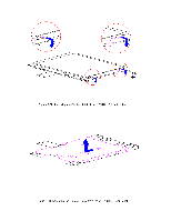
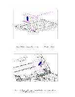
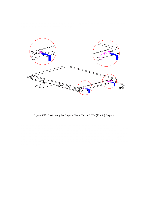
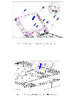
4. Place the display shield tabs in the indentations on the sides of the CSTN (10.4 in) panel (Figure 5-94). 5. Align the CSTN (10.4 in) panel, display cable, and shield in the display enclosure and replace the screws. Before replacing the screw in the lower-left corner, route the XOVER board ground wire around the boss at the bottom of the display enclosure. Hold the end of the wire over the screw hole and install the screw, attaching the wire. Ensure that the ZIF connector end of the display cable and the end of the display ground cable are exposed at the bottom of the display enclosure (Figure 5-95).
-
 1
1 -
2
-
3
-
4
-
5
-
6
-
7
-
8
-
9
-
10
-
11
-
12
-
13
-
14
-
15
-
16
-
17
-
18
-
19
-
20
-
21
-
22
-
23
-
24
-
25
-
26
-
27
-
28
-
29
-
30
-
31
-
32
-
33
-
34
-
35
-
36
-
37
-
38
-
39
-
40
-
41
-
42
-
43
-
44
-
45
-
46
-
47
-
48
-
49
-
50
-
51
-
52
-
53
-
54
-
55
-
56
-
57
-
58
-
59
-
60
-
61
-
62
-
63
-
64
-
65
-
66
-
67
-
68
-
69
-
70
-
71
-
72
-
73
-
74
-
75
-
76
-
77
-
78
-
79
-
80
-
81
-
82
-
83
-
84
-
85
-
86
-
87
-
88
-
89
-
90
-
91
-
92
-
93
-
94
-
95
-
96
-
97
-
98
-
99
-
100
-
101
-
102
-
103
-
104
-
105
-
106
-
107
-
108
-
109
-
110
-
111
-
112
-
113
-
114
-
115
-
116
-
117
-
118
-
119
-
120
-
121
-
122
-
123
-
124
-
125
-
126
-
127
-
128
-
129
-
130
-
131
-
132
-
133
-
134
-
135
-
136
-
137
-
138
-
139
-
140
-
 141
141 -
 142
142 -
 143
143 -
 144
144 -
 145
145 -
 146
146 -
 147
147 -
 148
148 -
 149
149 -
 150
150 -
 151
151 -
152
-
153
-
154
-
155
-
156
-
157
-
158
-
159
-
160
-
161
-
162
-
163
-
164
-
165
-
166
-
167
-
168
-
169
-
170
-
171
-
172
-
173
-
174
-
175
-
176
-
177
-
178
-
179
-
180
-
181
-
182
-
183
-
184
-
185
-
186
-
187
-
188
-
189
-
190
-
191
-
192
-
193
-
194
-
195
-
196
-
197
-
198
 |
 |
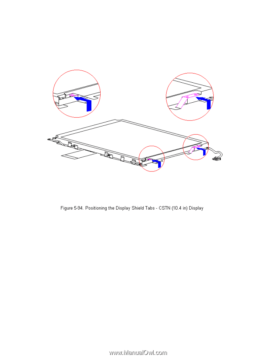
4. Place the display shield tabs in the indentations on the sides of the
CSTN (10.4 in) panel (Figure 5-94).
5. Align the CSTN (10.4 in) panel, display cable, and shield in the
display enclosure and replace the screws. Before replacing the screw in
the lower-left corner, route the XOVER board ground wire around the
boss at the bottom of the display enclosure.
Hold the end of the wire
over the screw hole and install the screw, attaching the wire.
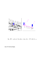
Ensure
that the ZIF connector end of the display cable and the end of the
display ground cable are exposed at the bottom of the display enclosure
(Figure 5-95).