HP Armada 1100 Armada 1100 Family of Personal Computers Maintenance and Servic - Page 78
Tilt Feet, Removing the Tilt Feet
 |
View all HP Armada 1100 manuals
Add to My Manuals
Save this manual to your list of manuals |
Page 78 highlights
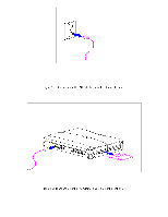
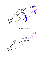
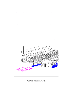
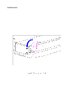
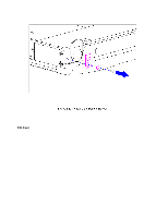
6. To install the handle bracket, reverse the previous steps. Discard the old screws and replace with new screws. Tilt Feet This procedure is necessary if replacing the tilt feet or if separating the display assembly from the system unit module. Removing the Tilt Feet To remove the tilt feet, follow these steps: 1. Turn the computer off and remove all external devices, including the battery pack and the AC Adapter. Remove the diskette and PC Card, if installed (Section 5.3). 2. Remove the tilt foot screw (Figure 5-9). Screws from the tilt feet are not reusable and must be discarded. 3. Remove the tilt foot (Figure 5-9).
-
 1
1 -
2
-
3
-
4
-
5
-
6
-
7
-
8
-
9
-
10
-
11
-
12
-
13
-
14
-
15
-
16
-
17
-
18
-
19
-
20
-
21
-
22
-
23
-
24
-
25
-
26
-
27
-
28
-
29
-
30
-
31
-
32
-
33
-
34
-
35
-
36
-
37
-
38
-
39
-
40
-
41
-
42
-
43
-
44
-
45
-
46
-
47
-
48
-
49
-
50
-
51
-
52
-
53
-
54
-
55
-
56
-
57
-
58
-
59
-
60
-
61
-
62
-
63
-
64
-
65
-
66
-
67
-
68
-
69
-
70
-
71
-
72
-
 73
73 -
 74
74 -
 75
75 -
 76
76 -
 77
77 -
 78
78 -
 79
79 -
 80
80 -
 81
81 -
 82
82 -
 83
83 -
84
-
85
-
86
-
87
-
88
-
89
-
90
-
91
-
92
-
93
-
94
-
95
-
96
-
97
-
98
-
99
-
100
-
101
-
102
-
103
-
104
-
105
-
106
-
107
-
108
-
109
-
110
-
111
-
112
-
113
-
114
-
115
-
116
-
117
-
118
-
119
-
120
-
121
-
122
-
123
-
124
-
125
-
126
-
127
-
128
-
129
-
130
-
131
-
132
-
133
-
134
-
135
-
136
-
137
-
138
-
139
-
140
-
141
-
142
-
143
-
144
-
145
-
146
-
147
-
148
-
149
-
150
-
151
-
152
-
153
-
154
-
155
-
156
-
157
-
158
-
159
-
160
-
161
-
162
-
163
-
164
-
165
-
166
-
167
-
168
-
169
-
170
-
171
-
172
-
173
-
174
-
175
-
176
-
177
-
178
-
179
-
180
-
181
-
182
-
183
-
184
-
185
-
186
-
187
-
188
-
189
-
190
-
191
-
192
-
193
-
194
-
195
-
196
-
197
-
198
 |
 |
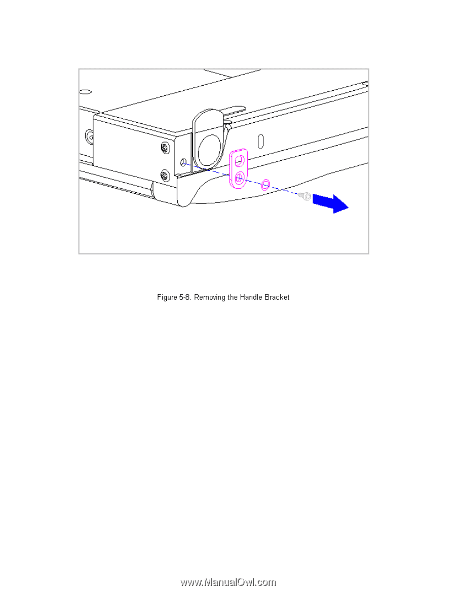
6. To install the handle bracket, reverse the previous steps. Discard the
old screws and replace with new screws.
Tilt Feet
This procedure is necessary if replacing the tilt feet or if separating the
display assembly from the system unit module.
Removing the Tilt Feet
To remove the tilt feet, follow these steps:
1. Turn the computer off and remove all external devices, including the
battery pack and the AC Adapter. Remove the diskette and PC Card, if
installed (Section 5.3).
2. Remove the tilt foot screw (Figure 5-9). Screws from the tilt feet are
not reusable and must be discarded.
3. Remove the tilt foot (Figure 5-9).