HP Armada 1100 Armada 1100 Family of Personal Computers Maintenance and Servic - Page 79
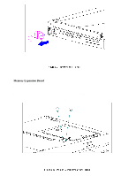
Memory Expansion Board, with arrows and two icons that indicate whether the memory compartment
 |
View all HP Armada 1100 manuals
Add to My Manuals
Save this manual to your list of manuals |
Page 79 highlights
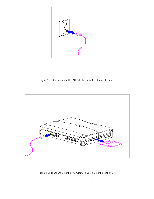
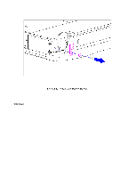
4. To install the tilt foot, reverse the previous steps. Discard the old screws and replace with new screws. Memory Expansion Board This section contains removal and replacement procedures for the memory compartment cover and the memory expansion board. The memory compartment cover and the bottom of the CPU base are embossed with arrows and two icons that indicate whether the memory compartment cover is unlocked [1] or locked [2] (Figure 5-10).
-
 1
1 -
2
-
3
-
4
-
5
-
6
-
7
-
8
-
9
-
10
-
11
-
12
-
13
-
14
-
15
-
16
-
17
-
18
-
19
-
20
-
21
-
22
-
23
-
24
-
25
-
26
-
27
-
28
-
29
-
30
-
31
-
32
-
33
-
34
-
35
-
36
-
37
-
38
-
39
-
40
-
41
-
42
-
43
-
44
-
45
-
46
-
47
-
48
-
49
-
50
-
51
-
52
-
53
-
54
-
55
-
56
-
57
-
58
-
59
-
60
-
61
-
62
-
63
-
64
-
65
-
66
-
67
-
68
-
69
-
70
-
71
-
72
-
73
-
 74
74 -
 75
75 -
 76
76 -
 77
77 -
 78
78 -
 79
79 -
 80
80 -
 81
81 -
 82
82 -
 83
83 -
 84
84 -
85
-
86
-
87
-
88
-
89
-
90
-
91
-
92
-
93
-
94
-
95
-
96
-
97
-
98
-
99
-
100
-
101
-
102
-
103
-
104
-
105
-
106
-
107
-
108
-
109
-
110
-
111
-
112
-
113
-
114
-
115
-
116
-
117
-
118
-
119
-
120
-
121
-
122
-
123
-
124
-
125
-
126
-
127
-
128
-
129
-
130
-
131
-
132
-
133
-
134
-
135
-
136
-
137
-
138
-
139
-
140
-
141
-
142
-
143
-
144
-
145
-
146
-
147
-
148
-
149
-
150
-
151
-
152
-
153
-
154
-
155
-
156
-
157
-
158
-
159
-
160
-
161
-
162
-
163
-
164
-
165
-
166
-
167
-
168
-
169
-
170
-
171
-
172
-
173
-
174
-
175
-
176
-
177
-
178
-
179
-
180
-
181
-
182
-
183
-
184
-
185
-
186
-
187
-
188
-
189
-
190
-
191
-
192
-
193
-
194
-
195
-
196
-
197
-
198
 |
 |
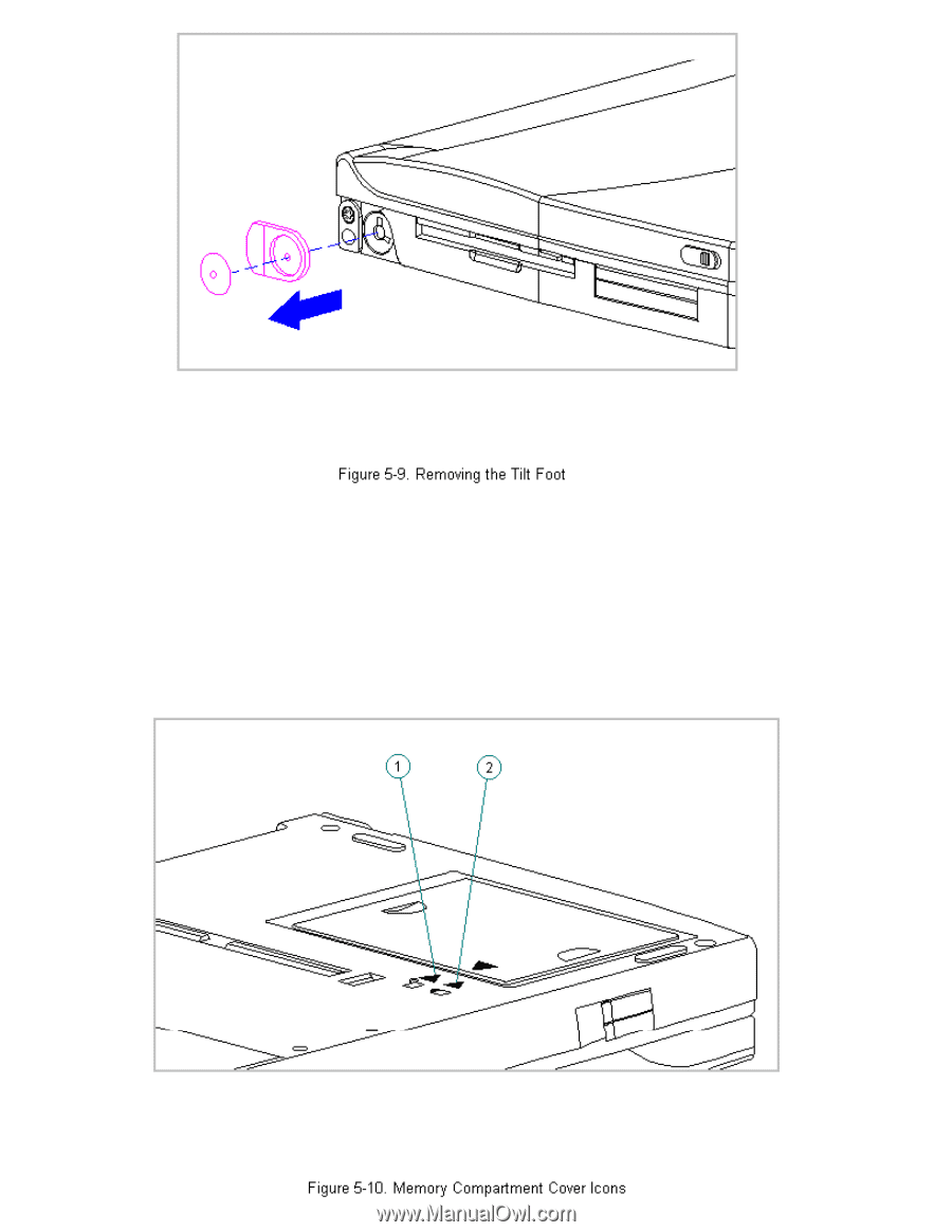
4. To install the tilt foot, reverse the previous steps. Discard the old
screws and replace with new screws.
Memory Expansion Board
This section contains removal and replacement procedures for the memory
compartment cover and the memory expansion board.
The memory compartment cover and the bottom of the CPU base are embossed
with arrows and two icons that indicate whether the memory compartment
cover is unlocked [1] or locked [2] (Figure 5-10).