HP Armada 1100 Armada 1100 Family of Personal Computers Maintenance and Servic - Page 137
Color STN 10.4 in Display, Removing the CSTN 10.4 in Panel, Shield, Display Cable, and the Display
 |
View all HP Armada 1100 manuals
Add to My Manuals
Save this manual to your list of manuals |
Page 137 highlights
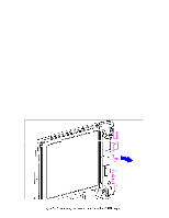
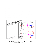
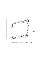
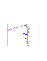
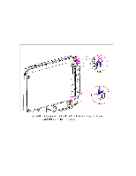
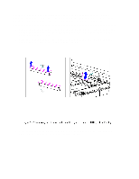
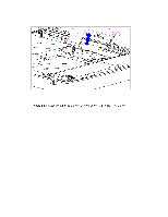
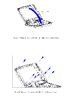
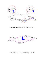
These steps must be followed whenever replacing any component in the display assembly because of high susceptibility to electrostatic discharge, which will damage the LCD panel. CAUTION When servicing the computer, ensure that cables are placed in their proper location to avoid pinching during the reassembly process. Improper cable placement can cause severe damage to the unit. 1. Insert the inverter board LIF connector into the display cable. 2. Plug in the backlight cable to the inverter board. 3. Mount the inverter board into the display enclosure, aligning the inverter board with the three mounting posts. 4. For the CSTN (10.4 in) display, reconnect the inverter ground wire to the lower right corner of the display. 5. For the CTFT (10.4 in) display, the inverter board slides partially underneath the display. Color STN (10.4 in) Display This section contains removal and replacement procedures for the following CSTN (10.4 in) display components: o Display panel o Shield o Display cable o Display ground cable Removing the CSTN (10.4 in) Panel, Shield, Display Cable, and the Display Ground Cable To remove the liquid crystal display CSTN (10.4 in) panel, shield, display cable, and the display ground cable, follow these steps: 1. Turn the computer off and remove all external devices, including the battery pack and the AC Adapter. Remove the diskette and PC Card, if installed (Section 5.3). 2. Open the computer. CAUTION The computer becomes top-heavy when the keyboard assembly is removed and the display is opened. To prevent damage to the display and the computer, ensure that the display assembly is opened at a 90-degree angle. 3. Remove the keyboard assembly (Section 5.7). CAUTION
-
 1
1 -
2
-
3
-
4
-
5
-
6
-
7
-
8
-
9
-
10
-
11
-
12
-
13
-
14
-
15
-
16
-
17
-
18
-
19
-
20
-
21
-
22
-
23
-
24
-
25
-
26
-
27
-
28
-
29
-
30
-
31
-
32
-
33
-
34
-
35
-
36
-
37
-
38
-
39
-
40
-
41
-
42
-
43
-
44
-
45
-
46
-
47
-
48
-
49
-
50
-
51
-
52
-
53
-
54
-
55
-
56
-
57
-
58
-
59
-
60
-
61
-
62
-
63
-
64
-
65
-
66
-
67
-
68
-
69
-
70
-
71
-
72
-
73
-
74
-
75
-
76
-
77
-
78
-
79
-
80
-
81
-
82
-
83
-
84
-
85
-
86
-
87
-
88
-
89
-
90
-
91
-
92
-
93
-
94
-
95
-
96
-
97
-
98
-
99
-
100
-
101
-
102
-
103
-
104
-
105
-
106
-
107
-
108
-
109
-
110
-
111
-
112
-
113
-
114
-
115
-
116
-
117
-
118
-
119
-
120
-
121
-
122
-
123
-
124
-
125
-
126
-
127
-
128
-
129
-
130
-
131
-
 132
132 -
 133
133 -
 134
134 -
 135
135 -
 136
136 -
 137
137 -
 138
138 -
 139
139 -
 140
140 -
 141
141 -
 142
142 -
143
-
144
-
145
-
146
-
147
-
148
-
149
-
150
-
151
-
152
-
153
-
154
-
155
-
156
-
157
-
158
-
159
-
160
-
161
-
162
-
163
-
164
-
165
-
166
-
167
-
168
-
169
-
170
-
171
-
172
-
173
-
174
-
175
-
176
-
177
-
178
-
179
-
180
-
181
-
182
-
183
-
184
-
185
-
186
-
187
-
188
-
189
-
190
-
191
-
192
-
193
-
194
-
195
-
196
-
197
-
198
 |
 |