HP Armada 1100 Armada 1100 Family of Personal Computers Maintenance and Servic - Page 155
Replacing the CTFT Display Cable, slide on the system board.
 |
View all HP Armada 1100 manuals
Add to My Manuals
Save this manual to your list of manuals |
Page 155 highlights
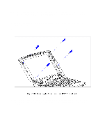
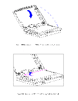
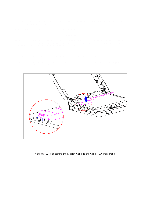
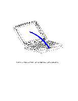
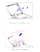
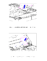
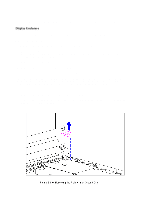
The ZIF connector and its attached cable can be damaged easily. Handle only the connector slide when disconnecting the ZIF connector. Never pull or twist the cable itself while it is seated in the ZIF connector. 8. Remove the display cable and backlight cable from the inverter board (Section 5.19). CAUTION When servicing the computer, ensure that cables are placed in their proper location to avoid pinching during the reassembly process. Improper cable placement can cause severe damage to the unit. 9. Remove the display panel. Refer to "Removing the CTFT (10.4 in) Display Panel" in this section. 10. Disconnect the display cable. Refer to "Removing the CTFT (10.4 in) Display Panel" in this section. Replacing the CTFT Display Cable To replace the CTFT (10.4 in) display cable, follow these steps: 1. Connect the display cable to the (10.4 in) panel. Refer to "Replacing the CTFT (10.4 in) Display Panel" in this section. 2. Connect the display cable and the backlight cable to the inverter board (Section 5.19). 3. Replace the inverter board (Section 5.19). 4. Replace the bezel (Section 5.19). 5. Carefully insert the end of the display cable into the ZIF connector slide on the system board. IMPORTANT: Ensure that the ZIF connector slide is in its fully upward position and that it remains so while you are inserting the cable into it. Before closing the slide, ensure that the cable is fully seated (to the white insertion line) in the ZIF connector. 6. While holding the end of the display cable inside the ZIF connector slide, press down both ends of the slide simultaneously to secure the cable in the ZIF connector (Figure 5-105).
-
 1
1 -
2
-
3
-
4
-
5
-
6
-
7
-
8
-
9
-
10
-
11
-
12
-
13
-
14
-
15
-
16
-
17
-
18
-
19
-
20
-
21
-
22
-
23
-
24
-
25
-
26
-
27
-
28
-
29
-
30
-
31
-
32
-
33
-
34
-
35
-
36
-
37
-
38
-
39
-
40
-
41
-
42
-
43
-
44
-
45
-
46
-
47
-
48
-
49
-
50
-
51
-
52
-
53
-
54
-
55
-
56
-
57
-
58
-
59
-
60
-
61
-
62
-
63
-
64
-
65
-
66
-
67
-
68
-
69
-
70
-
71
-
72
-
73
-
74
-
75
-
76
-
77
-
78
-
79
-
80
-
81
-
82
-
83
-
84
-
85
-
86
-
87
-
88
-
89
-
90
-
91
-
92
-
93
-
94
-
95
-
96
-
97
-
98
-
99
-
100
-
101
-
102
-
103
-
104
-
105
-
106
-
107
-
108
-
109
-
110
-
111
-
112
-
113
-
114
-
115
-
116
-
117
-
118
-
119
-
120
-
121
-
122
-
123
-
124
-
125
-
126
-
127
-
128
-
129
-
130
-
131
-
132
-
133
-
134
-
135
-
136
-
137
-
138
-
139
-
140
-
141
-
142
-
143
-
144
-
145
-
146
-
147
-
148
-
149
-
 150
150 -
 151
151 -
 152
152 -
 153
153 -
 154
154 -
 155
155 -
 156
156 -
 157
157 -
 158
158 -
 159
159 -
 160
160 -
161
-
162
-
163
-
164
-
165
-
166
-
167
-
168
-
169
-
170
-
171
-
172
-
173
-
174
-
175
-
176
-
177
-
178
-
179
-
180
-
181
-
182
-
183
-
184
-
185
-
186
-
187
-
188
-
189
-
190
-
191
-
192
-
193
-
194
-
195
-
196
-
197
-
198
 |
 |