HP Armada 1100 Armada 1100 Family of Personal Computers Maintenance and Servic - Page 114
Removing the PC Card PCMCIA Rails, Do not over tighten the clip, or it can become damaged.
 |
View all HP Armada 1100 manuals
Add to My Manuals
Save this manual to your list of manuals |
Page 114 highlights
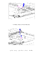
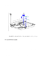
2. Remove the keyboard assembly (Section 5.7). 3. Remove the system board (Section 5.13). 4. Remove the two screws of the PC Card rails from the bottom of the system board (Figure 5-53). 5. Remove the clip from the top of the PC Card (PCMCIA) header (Figure 5-53). 6. To replace the PC Card clip, reverse the previous steps CAUTION Do not over tighten the clip, or it can become damaged CAUTION Be sure not to overtighten any screws or the PC Cards may be difficult to insert and eject Removing the PC Card (PCMCIA) Rails To remove the PC Card rails, follow these steps.
-
 1
1 -
2
-
3
-
4
-
5
-
6
-
7
-
8
-
9
-
10
-
11
-
12
-
13
-
14
-
15
-
16
-
17
-
18
-
19
-
20
-
21
-
22
-
23
-
24
-
25
-
26
-
27
-
28
-
29
-
30
-
31
-
32
-
33
-
34
-
35
-
36
-
37
-
38
-
39
-
40
-
41
-
42
-
43
-
44
-
45
-
46
-
47
-
48
-
49
-
50
-
51
-
52
-
53
-
54
-
55
-
56
-
57
-
58
-
59
-
60
-
61
-
62
-
63
-
64
-
65
-
66
-
67
-
68
-
69
-
70
-
71
-
72
-
73
-
74
-
75
-
76
-
77
-
78
-
79
-
80
-
81
-
82
-
83
-
84
-
85
-
86
-
87
-
88
-
89
-
90
-
91
-
92
-
93
-
94
-
95
-
96
-
97
-
98
-
99
-
100
-
101
-
102
-
103
-
104
-
105
-
106
-
107
-
108
-
 109
109 -
 110
110 -
 111
111 -
 112
112 -
 113
113 -
 114
114 -
 115
115 -
 116
116 -
 117
117 -
 118
118 -
 119
119 -
120
-
121
-
122
-
123
-
124
-
125
-
126
-
127
-
128
-
129
-
130
-
131
-
132
-
133
-
134
-
135
-
136
-
137
-
138
-
139
-
140
-
141
-
142
-
143
-
144
-
145
-
146
-
147
-
148
-
149
-
150
-
151
-
152
-
153
-
154
-
155
-
156
-
157
-
158
-
159
-
160
-
161
-
162
-
163
-
164
-
165
-
166
-
167
-
168
-
169
-
170
-
171
-
172
-
173
-
174
-
175
-
176
-
177
-
178
-
179
-
180
-
181
-
182
-
183
-
184
-
185
-
186
-
187
-
188
-
189
-
190
-
191
-
192
-
193
-
194
-
195
-
196
-
197
-
198
 |
 |
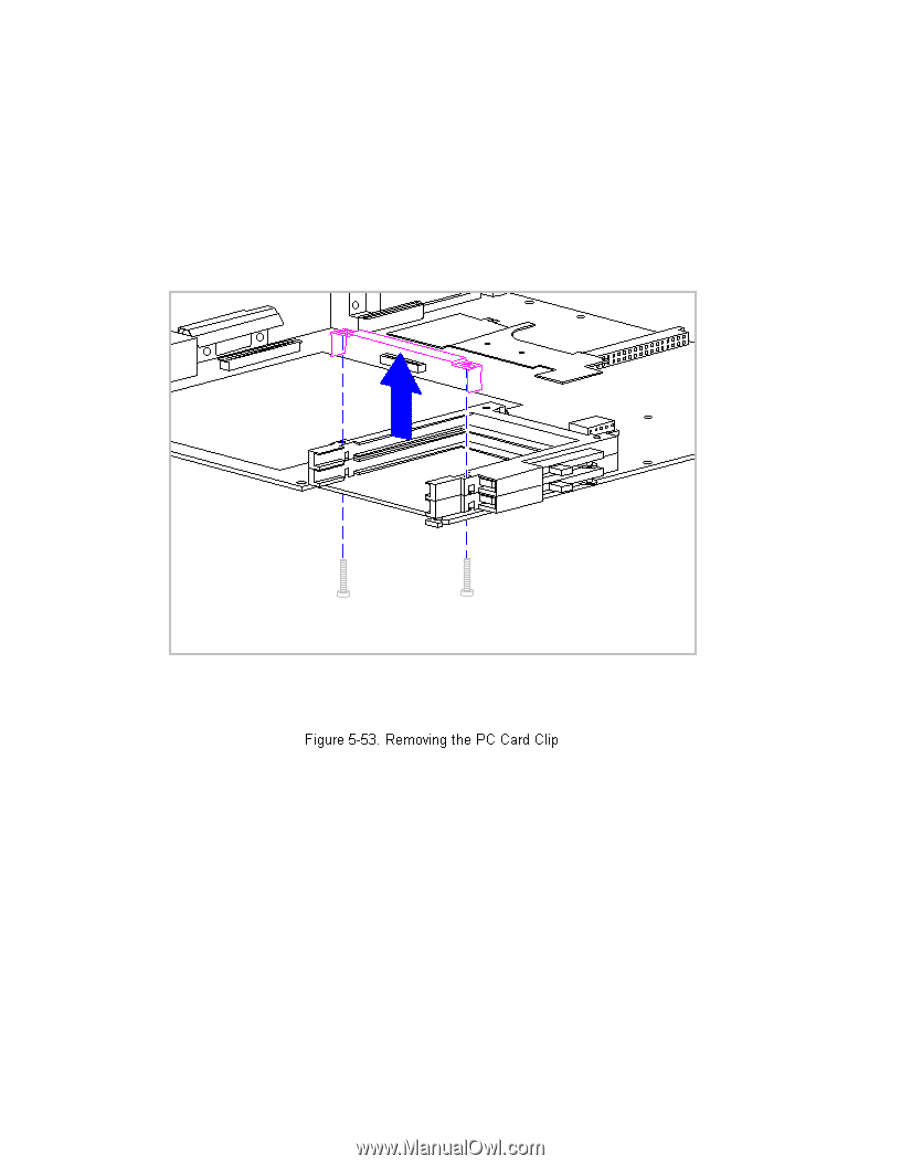
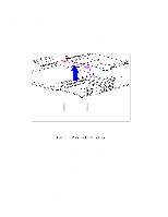
2. Remove the keyboard assembly (Section 5.7).
3. Remove the system board (Section 5.13).
4. Remove the two screws of the PC Card rails from the bottom of the system
board (Figure 5-53).
5. Remove the clip from the top of the PC Card (PCMCIA) header (Figure
5-53).
6. To replace the PC Card clip, reverse the previous steps.
>>>>>>>>>>>>>>>>>>>>>>>>>>>>>>>>> CAUTION <<<<<<<<<<<<<<<<<<<<<<<<<<<<<<<<<
Do not over tighten the clip, or it can become damaged.
>>>>>>>>>>>>>>>>>>>>>>>>>>>>>>>>>>>>><<<<<<<<<<<<<<<<<<<<<<<<<<<<<<<<<<<<<<
>>>>>>>>>>>>>>>>>>>>>>>>>>>>>>>>> CAUTION <<<<<<<<<<<<<<<<<<<<<<<<<<<<<<<<<
Be sure not to overtighten any screws or the PC Cards may be difficult to
insert and eject.
>>>>>>>>>>>>>>>>>>>>>>>>>>>>>>>>>>>>><<<<<<<<<<<<<<<<<<<<<<<<<<<<<<<<<<<<<<
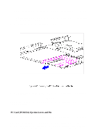
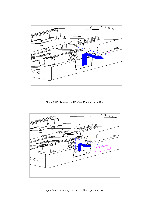
Removing the PC Card (PCMCIA) Rails
To remove the PC Card rails, follow these steps.