HP Armada 1100 Armada 1100 Family of Personal Computers Maintenance and Servic - Page 127
Display Assembly Components, oval outline on the CPU base and the battery tray
 |
View all HP Armada 1100 manuals
Add to My Manuals
Save this manual to your list of manuals |
Page 127 highlights
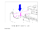
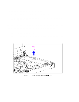
4. To replace the lock provision plate, reverse the previous steps. Attaching the Anti-Skid Pads If replacing the CPU base, two anti-skid pads for the battery tray and the two for the CPU base must be attached to the bottom of the base. To attach the anti-skid pads, follow these steps: 1. Peel off the top layer of one of the anti-skid pads to expose the adhesive. 2. With the adhesive side down, place the anti-skid pad into the raised oval outline on the CPU base and the battery tray (Figure 5-70). Display Assembly Components This section contains removal and replacement procedures for the following display assembly components:
-
 1
1 -
2
-
3
-
4
-
5
-
6
-
7
-
8
-
9
-
10
-
11
-
12
-
13
-
14
-
15
-
16
-
17
-
18
-
19
-
20
-
21
-
22
-
23
-
24
-
25
-
26
-
27
-
28
-
29
-
30
-
31
-
32
-
33
-
34
-
35
-
36
-
37
-
38
-
39
-
40
-
41
-
42
-
43
-
44
-
45
-
46
-
47
-
48
-
49
-
50
-
51
-
52
-
53
-
54
-
55
-
56
-
57
-
58
-
59
-
60
-
61
-
62
-
63
-
64
-
65
-
66
-
67
-
68
-
69
-
70
-
71
-
72
-
73
-
74
-
75
-
76
-
77
-
78
-
79
-
80
-
81
-
82
-
83
-
84
-
85
-
86
-
87
-
88
-
89
-
90
-
91
-
92
-
93
-
94
-
95
-
96
-
97
-
98
-
99
-
100
-
101
-
102
-
103
-
104
-
105
-
106
-
107
-
108
-
109
-
110
-
111
-
112
-
113
-
114
-
115
-
116
-
117
-
118
-
119
-
120
-
121
-
 122
122 -
 123
123 -
 124
124 -
 125
125 -
 126
126 -
 127
127 -
 128
128 -
 129
129 -
 130
130 -
 131
131 -
 132
132 -
133
-
134
-
135
-
136
-
137
-
138
-
139
-
140
-
141
-
142
-
143
-
144
-
145
-
146
-
147
-
148
-
149
-
150
-
151
-
152
-
153
-
154
-
155
-
156
-
157
-
158
-
159
-
160
-
161
-
162
-
163
-
164
-
165
-
166
-
167
-
168
-
169
-
170
-
171
-
172
-
173
-
174
-
175
-
176
-
177
-
178
-
179
-
180
-
181
-
182
-
183
-
184
-
185
-
186
-
187
-
188
-
189
-
190
-
191
-
192
-
193
-
194
-
195
-
196
-
197
-
198
 |
 |
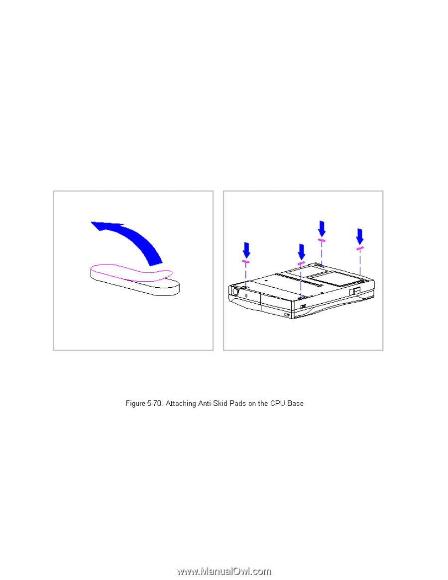
4. To replace the lock provision plate, reverse the previous steps.
Attaching the Anti-Skid Pads
If replacing the CPU base, two anti-skid pads for the battery tray and the
two for the CPU base must be attached to the bottom of the base. To attach
the anti-skid pads, follow these steps:
1. Peel off the top layer of one of the anti-skid pads to expose the
adhesive.
2. With the adhesive side down, place the anti-skid pad into the raised
oval outline on the CPU base and the battery tray (Figure 5-70).
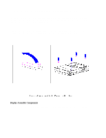
Display Assembly Components
This section contains removal and replacement procedures for the following
display assembly components: