HP Armada 1100 Armada 1100 Family of Personal Computers Maintenance and Servic - Page 168
While holding the end of the display cable inside the ZIF connector
 |
View all HP Armada 1100 manuals
Add to My Manuals
Save this manual to your list of manuals |
Page 168 highlights
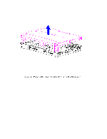
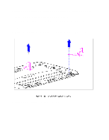
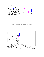
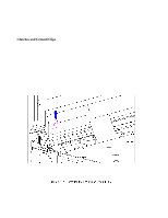
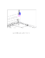
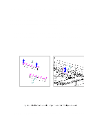
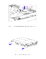
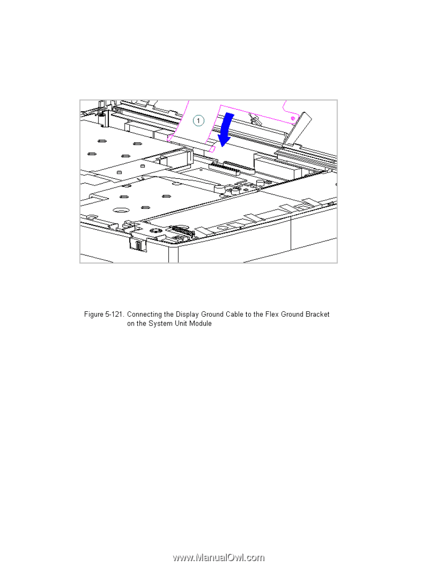
30. Connect the display ground cable [1] to the flex ground bracket above the serial port connector between the system board and the system chassis (Figure 5-121). 31. Carefully insert the end of the cable into the ZIF connector slide on the system unit. IMPORTANT: Ensure that the ZIF connector slide is in its fully upward position and that it remains so while you are inserting the cable into it. Before closing the slide, ensure that the cable is fully seated (to the white insertion line) in the ZIF connector. 32. While holding the end of the display cable inside the ZIF connector slide, press down both ends of the slide simultaneously to secure the cable in the ZIF connector (Figure 5-122).
-
 1
1 -
2
-
3
-
4
-
5
-
6
-
7
-
8
-
9
-
10
-
11
-
12
-
13
-
14
-
15
-
16
-
17
-
18
-
19
-
20
-
21
-
22
-
23
-
24
-
25
-
26
-
27
-
28
-
29
-
30
-
31
-
32
-
33
-
34
-
35
-
36
-
37
-
38
-
39
-
40
-
41
-
42
-
43
-
44
-
45
-
46
-
47
-
48
-
49
-
50
-
51
-
52
-
53
-
54
-
55
-
56
-
57
-
58
-
59
-
60
-
61
-
62
-
63
-
64
-
65
-
66
-
67
-
68
-
69
-
70
-
71
-
72
-
73
-
74
-
75
-
76
-
77
-
78
-
79
-
80
-
81
-
82
-
83
-
84
-
85
-
86
-
87
-
88
-
89
-
90
-
91
-
92
-
93
-
94
-
95
-
96
-
97
-
98
-
99
-
100
-
101
-
102
-
103
-
104
-
105
-
106
-
107
-
108
-
109
-
110
-
111
-
112
-
113
-
114
-
115
-
116
-
117
-
118
-
119
-
120
-
121
-
122
-
123
-
124
-
125
-
126
-
127
-
128
-
129
-
130
-
131
-
132
-
133
-
134
-
135
-
136
-
137
-
138
-
139
-
140
-
141
-
142
-
143
-
144
-
145
-
146
-
147
-
148
-
149
-
150
-
151
-
152
-
153
-
154
-
155
-
156
-
157
-
158
-
159
-
160
-
161
-
162
-
 163
163 -
 164
164 -
 165
165 -
 166
166 -
 167
167 -
 168
168 -
 169
169 -
 170
170 -
 171
171 -
 172
172 -
 173
173 -
174
-
175
-
176
-
177
-
178
-
179
-
180
-
181
-
182
-
183
-
184
-
185
-
186
-
187
-
188
-
189
-
190
-
191
-
192
-
193
-
194
-
195
-
196
-
197
-
198
 |
 |
30. Connect the display ground cable [1] to the flex ground bracket above
the serial port connector between the system board and the system
chassis (Figure 5-121).
31. Carefully insert the end of the cable into the ZIF connector slide on
the system unit.
IMPORTANT: Ensure that the ZIF connector slide is in its fully upward
position and that it remains so while you are inserting the
cable into it.
Before closing the slide, ensure that the cable
is fully seated (to the white insertion line) in the ZIF
connector.
32. While holding the end of the display cable inside the ZIF connector
slide, press down both ends of the slide simultaneously to secure the
slide, press
cable in the ZIF connector (Figure 5-122).
down both ends of the slide simultaneously to secure the