HP Armada 1100 Armada 1100 Family of Personal Computers Maintenance and Servic - Page 126
Removing and Replacing the Lock Provision Plate
 |
View all HP Armada 1100 manuals
Add to My Manuals
Save this manual to your list of manuals |
Page 126 highlights
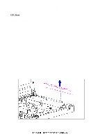
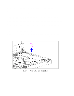
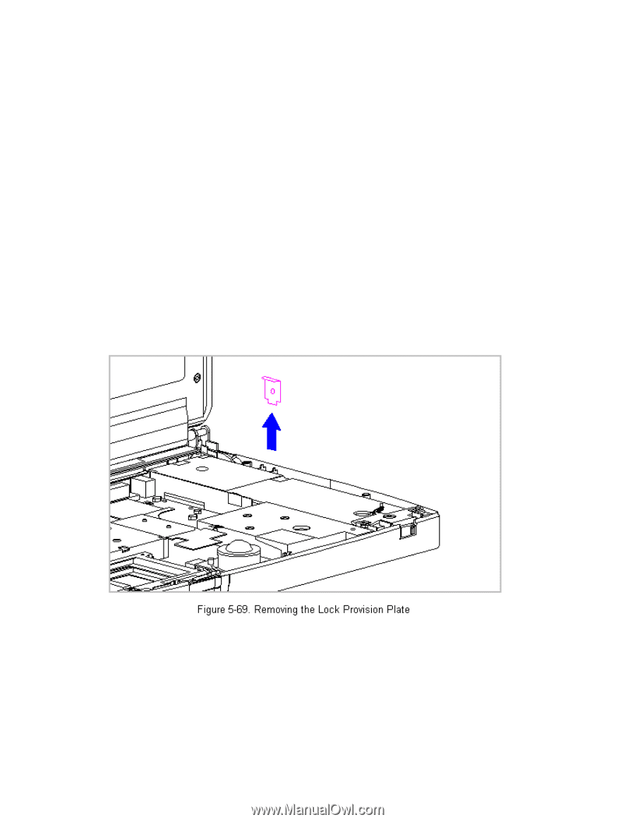
5. To replace the battery shield clip, reverse the previous steps. Removing and Replacing the Lock Provision Plate To remove the lock provision plate, follow these steps: 1. Turn the computer off and remove all external devices, including the battery pack and the AC Adapter. Remove the diskette and PC Card, if installed (Section 5.3). CAUTION The computer becomes top-heavy when the keyboard assembly is removed and the display is opened. To prevent damage to the display and the computer, ensure that the display assembly is opened at a 90-degree angle. 2. Remove the keyboard assembly (Section 5.7). 3. Remove the lock provision plate located between the battery enclosure and the right interior wall of the CPU base (Figure 5-69).
-
 1
1 -
2
-
3
-
4
-
5
-
6
-
7
-
8
-
9
-
10
-
11
-
12
-
13
-
14
-
15
-
16
-
17
-
18
-
19
-
20
-
21
-
22
-
23
-
24
-
25
-
26
-
27
-
28
-
29
-
30
-
31
-
32
-
33
-
34
-
35
-
36
-
37
-
38
-
39
-
40
-
41
-
42
-
43
-
44
-
45
-
46
-
47
-
48
-
49
-
50
-
51
-
52
-
53
-
54
-
55
-
56
-
57
-
58
-
59
-
60
-
61
-
62
-
63
-
64
-
65
-
66
-
67
-
68
-
69
-
70
-
71
-
72
-
73
-
74
-
75
-
76
-
77
-
78
-
79
-
80
-
81
-
82
-
83
-
84
-
85
-
86
-
87
-
88
-
89
-
90
-
91
-
92
-
93
-
94
-
95
-
96
-
97
-
98
-
99
-
100
-
101
-
102
-
103
-
104
-
105
-
106
-
107
-
108
-
109
-
110
-
111
-
112
-
113
-
114
-
115
-
116
-
117
-
118
-
119
-
120
-
 121
121 -
 122
122 -
 123
123 -
 124
124 -
 125
125 -
 126
126 -
 127
127 -
 128
128 -
 129
129 -
 130
130 -
 131
131 -
132
-
133
-
134
-
135
-
136
-
137
-
138
-
139
-
140
-
141
-
142
-
143
-
144
-
145
-
146
-
147
-
148
-
149
-
150
-
151
-
152
-
153
-
154
-
155
-
156
-
157
-
158
-
159
-
160
-
161
-
162
-
163
-
164
-
165
-
166
-
167
-
168
-
169
-
170
-
171
-
172
-
173
-
174
-
175
-
176
-
177
-
178
-
179
-
180
-
181
-
182
-
183
-
184
-
185
-
186
-
187
-
188
-
189
-
190
-
191
-
192
-
193
-
194
-
195
-
196
-
197
-
198
 |
 |
5. To replace the battery shield clip, reverse the previous steps.
Removing and Replacing the Lock Provision Plate
To remove the lock provision plate, follow these steps:
1. Turn the computer off and remove all external devices, including the
battery pack and the AC Adapter. Remove the diskette and PC Card, if
installed (Section 5.3).
>>>>>>>>>>>>>>>>>>>>>>>>>>>>>>>>> CAUTION <<<<<<<<<<<<<<<<<<<<<<<<<<<<<<<<<
The computer becomes top-heavy when the keyboard assembly is removed and
the display is opened. To prevent damage to the display and the computer,
ensure that the display assembly is opened at a 90-degree angle.
>>>>>>>>>>>>>>>>>>>>>>>>>>>>>>>>>>>>><<<<<<<<<<<<<<<<<<<<<<<<<<<<<<<<<<<<<<
2. Remove the keyboard assembly (Section 5.7).
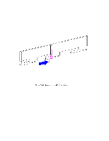
3. Remove the lock provision plate located between the battery enclosure
and the right interior wall of the CPU base (Figure 5-69).