Lenovo ThinkStation P700 (English) User Guide - ThinkStation P500 (type 30A6, - Page 98
Replacing the front fan assembly
 |
View all Lenovo ThinkStation P700 manuals
Add to My Manuals
Save this manual to your list of manuals |
Page 98 highlights
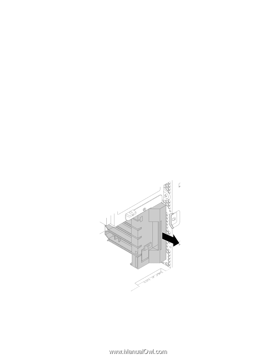
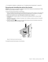
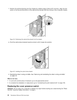
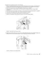
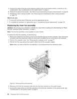
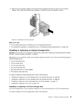
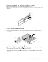
9. Connect the cable of the new cover presence switch to the cover presence switch connector on the system board. See "Locating parts on the system board" on page 6. 10. Reinstall the optical drive bracket. See "Removing and reinstalling the optical drive bracket" on page 83. 11. Reinstall the direct cooling air baffle. See "Removing and reinstalling the direct cooling air baffle" on page 78. What to do next: • To work with another piece of hardware, go to the appropriate section. • To complete the installation or replacement, go to "Completing the parts replacement" on page 130. Replacing the front fan assembly Attention: Do not open your computer or attempt any repair before reading and understanding the "Read this first: Important safety information" on page v. Note: The front fan assembly is only available on some models. To replace the front fan assembly, do the following: 1. Remove all media from the drives and turn off all attached devices and the computer. Then, disconnect all power cords from electrical outlets and disconnect all cables that are connected to the computer. 2. Remove the computer cover. See "Removing the computer cover" on page 77. 3. Pull the front fan assembly by the handle to slide it out of the computer chassis. Note: When you slide out the front fan assembly, avoid pulling the front fan assembly cable. Figure 23. Removing the front fan assembly 4. Disconnect the front fan assembly cable from the front fan connector on the system board. 5. Connect the cable of the new front fan assembly to the front fan connector on the system board. See "Locating parts on the system board" on page 6. 86 ThinkStation P500 and P700 User Guide
-
 1
1 -
2
-
3
-
4
-
5
-
6
-
7
-
8
-
9
-
10
-
11
-
12
-
13
-
14
-
15
-
16
-
17
-
18
-
19
-
20
-
21
-
22
-
23
-
24
-
25
-
26
-
27
-
28
-
29
-
30
-
31
-
32
-
33
-
34
-
35
-
36
-
37
-
38
-
39
-
40
-
41
-
42
-
43
-
44
-
45
-
46
-
47
-
48
-
49
-
50
-
51
-
52
-
53
-
54
-
55
-
56
-
57
-
58
-
59
-
60
-
61
-
62
-
63
-
64
-
65
-
66
-
67
-
68
-
69
-
70
-
71
-
72
-
73
-
74
-
75
-
76
-
77
-
78
-
79
-
80
-
81
-
82
-
83
-
84
-
85
-
86
-
87
-
88
-
89
-
90
-
91
-
92
-
 93
93 -
 94
94 -
 95
95 -
 96
96 -
 97
97 -
 98
98 -
 99
99 -
 100
100 -
 101
101 -
 102
102 -
 103
103 -
104
-
105
-
106
-
107
-
108
-
109
-
110
-
111
-
112
-
113
-
114
-
115
-
116
-
117
-
118
-
119
-
120
-
121
-
122
-
123
-
124
-
125
-
126
-
127
-
128
-
129
-
130
-
131
-
132
-
133
-
134
-
135
-
136
-
137
-
138
-
139
-
140
-
141
-
142
-
143
-
144
-
145
-
146
-
147
-
148
-
149
-
150
-
151
-
152
-
153
-
154
-
155
-
156
-
157
-
158
-
159
-
160
-
161
-
162
-
163
-
164
-
165
-
166
-
167
-
168
-
169
-
170
 |
 |