Netgear GS728TPP GS728TP/GS728TPP/GS752TP Software Administration Manual - Page 129
TTagged, UUntagged, BLANKAutodetect, APPLY, In the VLAN ID field specify a VLAN ID.
 |
View all Netgear GS728TPP manuals
Add to My Manuals
Save this manual to your list of manuals |
Page 129 highlights
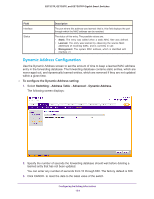
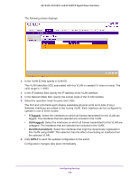
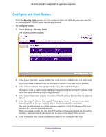
GS752TP, GS728TP, and GS728TPP Gigabit Smart Switches The following screen displays: 2. In the VLAN ID field specify a VLAN ID. This VLAN identifier (VID) associated with this VLAN is created if it does not exist. The valid range is 1-4093. 3. In the IP Address field, specify the IP address of the VLAN interface. 4. In the Network Mask field, specify the subnet mask of the VLAN interface. 5. Select the operation mode for ports and LAGs. The Port and LAG fields each display selectable physical ports and LAGs (if any). Selected interfaces are added to the routing VLAN. Each interface can be configured to operate in one of three modes: • T(Tagged). Select the interfaces on which all frames transmitted for this VLAN are tagged. The interfaces that are selected are included in the VLAN. • U(Untagged). Select the interfaces on which all frames transmitted for this VLAN are untagged. The interfaces that are selected are included in the VLAN. • BLANK(Autodetect). Select the interfaces that might be dynamically registered in this VLAN using GVRP. This selection has the effect of excluding an interface from the selected VLAN. 6. Click APPLY to send the updated configuration to the switch. Configuration changes take place immediately. Configuring Routing 129
-
 1
1 -
2
-
3
-
4
-
5
-
6
-
7
-
8
-
9
-
10
-
11
-
12
-
13
-
14
-
15
-
16
-
17
-
18
-
19
-
20
-
21
-
22
-
23
-
24
-
25
-
26
-
27
-
28
-
29
-
30
-
31
-
32
-
33
-
34
-
35
-
36
-
37
-
38
-
39
-
40
-
41
-
42
-
43
-
44
-
45
-
46
-
47
-
48
-
49
-
50
-
51
-
52
-
53
-
54
-
55
-
56
-
57
-
58
-
59
-
60
-
61
-
62
-
63
-
64
-
65
-
66
-
67
-
68
-
69
-
70
-
71
-
72
-
73
-
74
-
75
-
76
-
77
-
78
-
79
-
80
-
81
-
82
-
83
-
84
-
85
-
86
-
87
-
88
-
89
-
90
-
91
-
92
-
93
-
94
-
95
-
96
-
97
-
98
-
99
-
100
-
101
-
102
-
103
-
104
-
105
-
106
-
107
-
108
-
109
-
110
-
111
-
112
-
113
-
114
-
115
-
116
-
117
-
118
-
119
-
120
-
121
-
122
-
123
-
 124
124 -
 125
125 -
 126
126 -
 127
127 -
 128
128 -
 129
129 -
 130
130 -
 131
131 -
 132
132 -
 133
133 -
 134
134 -
135
-
136
-
137
-
138
-
139
-
140
-
141
-
142
-
143
-
144
-
145
-
146
-
147
-
148
-
149
-
150
-
151
-
152
-
153
-
154
-
155
-
156
-
157
-
158
-
159
-
160
-
161
-
162
-
163
-
164
-
165
-
166
-
167
-
168
-
169
-
170
-
171
-
172
-
173
-
174
-
175
-
176
-
177
-
178
-
179
-
180
-
181
-
182
-
183
-
184
-
185
-
186
-
187
-
188
-
189
-
190
-
191
-
192
-
193
-
194
-
195
-
196
-
197
-
198
-
199
-
200
-
201
-
202
-
203
-
204
-
205
-
206
-
207
-
208
-
209
-
210
-
211
-
212
-
213
-
214
-
215
-
216
-
217
-
218
-
219
-
220
-
221
-
222
-
223
-
224
-
225
-
226
-
227
-
228
-
229
-
230
-
231
-
232
-
233
-
234
-
235
-
236
-
237
-
238
-
239
-
240
-
241
-
242
-
243
-
244
-
245
-
246
-
247
-
248
-
249
-
250
-
251
-
252
-
253
-
254
-
255
-
256
-
257
-
258
-
259
-
260
-
261
-
262
-
263
-
264
-
265
-
266
-
267
-
268
-
269
-
270
-
271
-
272
-
273
-
274
-
275
 |
 |
