Netgear GS728TPP GS728TP/GS728TPP/GS752TP Software Administration Manual - Page 40
Green Ethernet Detail, To con the Green Ethernet Detail feature
 |
View all Netgear GS728TPP manuals
Add to My Manuals
Save this manual to your list of manuals |
Page 40 highlights
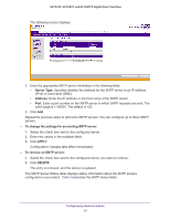
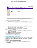
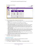
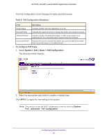
GS752TP, GS728TP, and GS728TPP Gigabit Smart Switches The following screen displays: 2. Select the following interface settings for the physical port: • Go To Interface. Enter a port identifier (appears in the Port column) and click the Go button. The table entry corresponding to the specified port is selected. • Port. Selects the interface for which data is displayed or configured. • Auto Power Down Mode. Determines whether Auto Power Down mode is enabled for the port. The factory default is Disable. When the port link is down, the PHY automatically goes down for a short period and wakes up to check link pulses. This mode allows automatic negotiation and reduces power consumption when no link partner is present. • Short Cable Mode. Determines whether Short Cable mode is enabled for the port. The factory default is Disable. When the port link up at 1 Gbps, the cable length test is performed. If the length of the cable is less than 10 meters, PHYs are put into low-power mode so enough power is used to support a short cable. Do not enable both EEE and Short Cable modes for a port. • EEE Mode. Determines whether Energy Efficient Ethernet (EEE) mode is enabled for the port. Do not enable both EEE and Short Cable modes for a port. 3. Click APPLY to apply the change to the system. Configuration changes take effect immediately. Green Ethernet Detail Use this screen to display or configure Green Ethernet details per interface. To configure the Green Ethernet Detail feature: 1. Select System Management Green Ethernet Green Ethernet Detail. Configuring System Information 40
-
 1
1 -
2
-
3
-
4
-
5
-
6
-
7
-
8
-
9
-
10
-
11
-
12
-
13
-
14
-
15
-
16
-
17
-
18
-
19
-
20
-
21
-
22
-
23
-
24
-
25
-
26
-
27
-
28
-
29
-
30
-
31
-
32
-
33
-
34
-
 35
35 -
 36
36 -
 37
37 -
 38
38 -
 39
39 -
 40
40 -
 41
41 -
 42
42 -
 43
43 -
 44
44 -
 45
45 -
46
-
47
-
48
-
49
-
50
-
51
-
52
-
53
-
54
-
55
-
56
-
57
-
58
-
59
-
60
-
61
-
62
-
63
-
64
-
65
-
66
-
67
-
68
-
69
-
70
-
71
-
72
-
73
-
74
-
75
-
76
-
77
-
78
-
79
-
80
-
81
-
82
-
83
-
84
-
85
-
86
-
87
-
88
-
89
-
90
-
91
-
92
-
93
-
94
-
95
-
96
-
97
-
98
-
99
-
100
-
101
-
102
-
103
-
104
-
105
-
106
-
107
-
108
-
109
-
110
-
111
-
112
-
113
-
114
-
115
-
116
-
117
-
118
-
119
-
120
-
121
-
122
-
123
-
124
-
125
-
126
-
127
-
128
-
129
-
130
-
131
-
132
-
133
-
134
-
135
-
136
-
137
-
138
-
139
-
140
-
141
-
142
-
143
-
144
-
145
-
146
-
147
-
148
-
149
-
150
-
151
-
152
-
153
-
154
-
155
-
156
-
157
-
158
-
159
-
160
-
161
-
162
-
163
-
164
-
165
-
166
-
167
-
168
-
169
-
170
-
171
-
172
-
173
-
174
-
175
-
176
-
177
-
178
-
179
-
180
-
181
-
182
-
183
-
184
-
185
-
186
-
187
-
188
-
189
-
190
-
191
-
192
-
193
-
194
-
195
-
196
-
197
-
198
-
199
-
200
-
201
-
202
-
203
-
204
-
205
-
206
-
207
-
208
-
209
-
210
-
211
-
212
-
213
-
214
-
215
-
216
-
217
-
218
-
219
-
220
-
221
-
222
-
223
-
224
-
225
-
226
-
227
-
228
-
229
-
230
-
231
-
232
-
233
-
234
-
235
-
236
-
237
-
238
-
239
-
240
-
241
-
242
-
243
-
244
-
245
-
246
-
247
-
248
-
249
-
250
-
251
-
252
-
253
-
254
-
255
-
256
-
257
-
258
-
259
-
260
-
261
-
262
-
263
-
264
-
265
-
266
-
267
-
268
-
269
-
270
-
271
-
272
-
273
-
274
-
275
 |
 |