Netgear GS728TPP GS728TP/GS728TPP/GS752TP Software Administration Manual - Page 191
MAC ACL, APPLY, To con a MAC ACL, Security, Basic > MAC ACL
 |
View all Netgear GS728TPP manuals
Add to My Manuals
Save this manual to your list of manuals |
Page 191 highlights
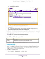
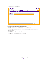
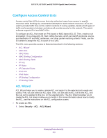
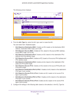
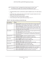
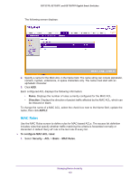
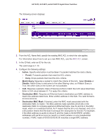
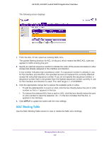
GS752TP, GS728TP, and GS728TPP Gigabit Smart Switches ACL Based on Fields Destination IPv6 L4 • Destination L4 port (protocol). Specify the destination IPv6 L4 port protocol. Port • Destination L4 port (value). Specify the destination IPv6 L4 port value. Source IPv6 L4 Port • Source L4 port (protocol). Specify the source IPv6 L4 port protocol. • Source L4 port (value). Specify the source IPv6 L4 port value. 4. In the Binding Configuration area, the Inbound only packet filtering direction for an ACL is selected in the Direction field. 5. In the Port Selection Table area, specify the list of all available valid interfaces for ACL mapping. All non-routing physical interfaces and interfaces participating in the LAG are listed. 6. To add a rule to the ACL, select the check box next to the ACL, then click ADD. 7. Click APPLY to update the switch with the new settings. Configuration changes take effect immediately. MAC ACL A MAC ACL consists of a set of rules that are matched sequentially against a packet. When a packet meets the match criteria of a rule, the specified rule action (permit or deny) is taken and the additional rules are not checked for a match. The steps for defining a MAC ACL and applying it to the switch are described in the following sections: 1. Use the MAC ACL screen to create the ACL ID. 2. Use the MAC Rules screen to create rules for the ACL. 3. Use the MAC Binding Configuration screen to assign the ACL by its ID number to a port. 4. Optionally, use the MAC Binding Table screen to view the configurations. To configure a MAC ACL: 1. Select Security ACL > Basic > MAC ACL. Managing Device Security 191
-
 1
1 -
2
-
3
-
4
-
5
-
6
-
7
-
8
-
9
-
10
-
11
-
12
-
13
-
14
-
15
-
16
-
17
-
18
-
19
-
20
-
21
-
22
-
23
-
24
-
25
-
26
-
27
-
28
-
29
-
30
-
31
-
32
-
33
-
34
-
35
-
36
-
37
-
38
-
39
-
40
-
41
-
42
-
43
-
44
-
45
-
46
-
47
-
48
-
49
-
50
-
51
-
52
-
53
-
54
-
55
-
56
-
57
-
58
-
59
-
60
-
61
-
62
-
63
-
64
-
65
-
66
-
67
-
68
-
69
-
70
-
71
-
72
-
73
-
74
-
75
-
76
-
77
-
78
-
79
-
80
-
81
-
82
-
83
-
84
-
85
-
86
-
87
-
88
-
89
-
90
-
91
-
92
-
93
-
94
-
95
-
96
-
97
-
98
-
99
-
100
-
101
-
102
-
103
-
104
-
105
-
106
-
107
-
108
-
109
-
110
-
111
-
112
-
113
-
114
-
115
-
116
-
117
-
118
-
119
-
120
-
121
-
122
-
123
-
124
-
125
-
126
-
127
-
128
-
129
-
130
-
131
-
132
-
133
-
134
-
135
-
136
-
137
-
138
-
139
-
140
-
141
-
142
-
143
-
144
-
145
-
146
-
147
-
148
-
149
-
150
-
151
-
152
-
153
-
154
-
155
-
156
-
157
-
158
-
159
-
160
-
161
-
162
-
163
-
164
-
165
-
166
-
167
-
168
-
169
-
170
-
171
-
172
-
173
-
174
-
175
-
176
-
177
-
178
-
179
-
180
-
181
-
182
-
183
-
184
-
185
-
 186
186 -
 187
187 -
 188
188 -
 189
189 -
 190
190 -
 191
191 -
 192
192 -
 193
193 -
 194
194 -
 195
195 -
 196
196 -
197
-
198
-
199
-
200
-
201
-
202
-
203
-
204
-
205
-
206
-
207
-
208
-
209
-
210
-
211
-
212
-
213
-
214
-
215
-
216
-
217
-
218
-
219
-
220
-
221
-
222
-
223
-
224
-
225
-
226
-
227
-
228
-
229
-
230
-
231
-
232
-
233
-
234
-
235
-
236
-
237
-
238
-
239
-
240
-
241
-
242
-
243
-
244
-
245
-
246
-
247
-
248
-
249
-
250
-
251
-
252
-
253
-
254
-
255
-
256
-
257
-
258
-
259
-
260
-
261
-
262
-
263
-
264
-
265
-
266
-
267
-
268
-
269
-
270
-
271
-
272
-
273
-
274
-
275
 |
 |