Netgear GS728TPP GS728TP/GS728TPP/GS752TP Software Administration Manual - Page 85
Port VLAN ID Configuration, Tag All, Remove All, APPLY, To con PVID information, Switching
 |
View all Netgear GS728TPP manuals
Add to My Manuals
Save this manual to your list of manuals |
Page 85 highlights
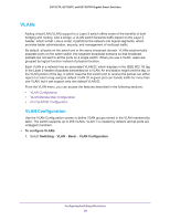
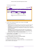
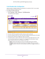
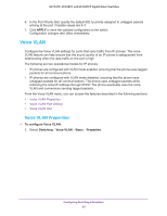
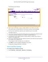
GS752TP, GS728TP, and GS728TPP Gigabit Smart Switches In the following screen, ports 6, 7, and 8 are being added as tagged members to VLAN 2. 6. From the Group Operations list, select an identical configuration for all the ports. The possible values are: • Tag All. All frames transmitted for this VLAN are tagged. All the ports are included in the VLAN. • Untag All. All frames transmitted from this VLAN are untagged. All the ports are included in the VLAN. • Remove All. Exclude all ports from the selected VLAN. 7. Click APPLY to send the updated configuration to the switch. Configuration changes take effect immediately. Port VLAN ID Configuration The Port PVID Configuration screen lets you assign a port VLAN ID (PVID) to an interface. A PVID has the following requirements: • All ports must have a defined PVID. • If no other value is specified, the default VLAN PVID is used. • If you want to change the port's default PVID, you must first create a VLAN that includes the port as a member. • Use the Port VLAN ID (PVID) Configuration screen to configure a virtual LAN on a port. To configure PVID information: 1. Select Switching VLAN Advanced Port PVID Configuration. Configuring Switching Information 85
-
 1
1 -
2
-
3
-
4
-
5
-
6
-
7
-
8
-
9
-
10
-
11
-
12
-
13
-
14
-
15
-
16
-
17
-
18
-
19
-
20
-
21
-
22
-
23
-
24
-
25
-
26
-
27
-
28
-
29
-
30
-
31
-
32
-
33
-
34
-
35
-
36
-
37
-
38
-
39
-
40
-
41
-
42
-
43
-
44
-
45
-
46
-
47
-
48
-
49
-
50
-
51
-
52
-
53
-
54
-
55
-
56
-
57
-
58
-
59
-
60
-
61
-
62
-
63
-
64
-
65
-
66
-
67
-
68
-
69
-
70
-
71
-
72
-
73
-
74
-
75
-
76
-
77
-
78
-
79
-
 80
80 -
 81
81 -
 82
82 -
 83
83 -
 84
84 -
 85
85 -
 86
86 -
 87
87 -
 88
88 -
 89
89 -
 90
90 -
91
-
92
-
93
-
94
-
95
-
96
-
97
-
98
-
99
-
100
-
101
-
102
-
103
-
104
-
105
-
106
-
107
-
108
-
109
-
110
-
111
-
112
-
113
-
114
-
115
-
116
-
117
-
118
-
119
-
120
-
121
-
122
-
123
-
124
-
125
-
126
-
127
-
128
-
129
-
130
-
131
-
132
-
133
-
134
-
135
-
136
-
137
-
138
-
139
-
140
-
141
-
142
-
143
-
144
-
145
-
146
-
147
-
148
-
149
-
150
-
151
-
152
-
153
-
154
-
155
-
156
-
157
-
158
-
159
-
160
-
161
-
162
-
163
-
164
-
165
-
166
-
167
-
168
-
169
-
170
-
171
-
172
-
173
-
174
-
175
-
176
-
177
-
178
-
179
-
180
-
181
-
182
-
183
-
184
-
185
-
186
-
187
-
188
-
189
-
190
-
191
-
192
-
193
-
194
-
195
-
196
-
197
-
198
-
199
-
200
-
201
-
202
-
203
-
204
-
205
-
206
-
207
-
208
-
209
-
210
-
211
-
212
-
213
-
214
-
215
-
216
-
217
-
218
-
219
-
220
-
221
-
222
-
223
-
224
-
225
-
226
-
227
-
228
-
229
-
230
-
231
-
232
-
233
-
234
-
235
-
236
-
237
-
238
-
239
-
240
-
241
-
242
-
243
-
244
-
245
-
246
-
247
-
248
-
249
-
250
-
251
-
252
-
253
-
254
-
255
-
256
-
257
-
258
-
259
-
260
-
261
-
262
-
263
-
264
-
265
-
266
-
267
-
268
-
269
-
270
-
271
-
272
-
273
-
274
-
275
 |
 |