Netgear GS728TPP GS728TP/GS728TPP/GS752TP Software Administration Manual - Page 24
Interface Naming Convention, GS752TP
 |
View all Netgear GS728TPP manuals
Add to My Manuals
Save this manual to your list of manuals |
Page 24 highlights
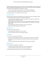
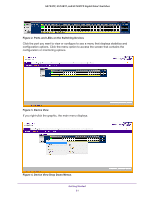
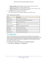
GS752TP, GS728TP, and GS728TPP Gigabit Smart Switches Interface Naming Convention The switch supports physical and logical interfaces. Interfaces are identified by their type and the interface number. The switches support the following ports: • GS752TP. Ports 1-48 are 10/100/1000M AutoSensing Gigabit ports, and ports 49-52 are 100/1000M SFP ports. The first 8 ports are PoE+ providing 30W of DC power, and the remaining copper ports are PoE (Power over Environment) providing 15.4W of DC power. • GS728TP. Ports 1-24 are 10/100/1000M AutoSensing Gigabit ports, and ports 25-28 are 100/1000M SFP ports. The first 8 ports are PoE+ providing 30W of DC power, and the remaining copper ports are PoE (Power over Environment) providing 15.4W of DC power. • GS728TPP. Ports 1-24 are 10/100/1000M AutoSensing Gigabit ports, and ports 25-28 are 100/1000M SFP ports. All 24 copper ports are PoE+ providing 30W of DC power. This model includes an external power supply to support the increased power requirements. The number of the port is identified on the front panel. You can configure the logical interfaces by using the software. The following table describes the naming convention for all interfaces available on the switch. Table 3. Naming Convention for Switch Interfaces Interface Description Example Physical The physical ports include Gigabit ports and are numbered g1, g2, g3 sequentially starting from 1. Link aggregation group (LAG) LAG interfaces are logical interfaces that are used only for l1, l2, l3 bridging functions. CPU Management Interface This is the internal switch interface responsible for the c1 switch base MAC address. This interface is not configurable and is always listed in the MAC Address Table. Getting Started 24
-
 1
1 -
2
-
3
-
4
-
5
-
6
-
7
-
8
-
9
-
10
-
11
-
12
-
13
-
14
-
15
-
16
-
17
-
18
-
 19
19 -
 20
20 -
 21
21 -
 22
22 -
 23
23 -
 24
24 -
 25
25 -
 26
26 -
 27
27 -
 28
28 -
 29
29 -
30
-
31
-
32
-
33
-
34
-
35
-
36
-
37
-
38
-
39
-
40
-
41
-
42
-
43
-
44
-
45
-
46
-
47
-
48
-
49
-
50
-
51
-
52
-
53
-
54
-
55
-
56
-
57
-
58
-
59
-
60
-
61
-
62
-
63
-
64
-
65
-
66
-
67
-
68
-
69
-
70
-
71
-
72
-
73
-
74
-
75
-
76
-
77
-
78
-
79
-
80
-
81
-
82
-
83
-
84
-
85
-
86
-
87
-
88
-
89
-
90
-
91
-
92
-
93
-
94
-
95
-
96
-
97
-
98
-
99
-
100
-
101
-
102
-
103
-
104
-
105
-
106
-
107
-
108
-
109
-
110
-
111
-
112
-
113
-
114
-
115
-
116
-
117
-
118
-
119
-
120
-
121
-
122
-
123
-
124
-
125
-
126
-
127
-
128
-
129
-
130
-
131
-
132
-
133
-
134
-
135
-
136
-
137
-
138
-
139
-
140
-
141
-
142
-
143
-
144
-
145
-
146
-
147
-
148
-
149
-
150
-
151
-
152
-
153
-
154
-
155
-
156
-
157
-
158
-
159
-
160
-
161
-
162
-
163
-
164
-
165
-
166
-
167
-
168
-
169
-
170
-
171
-
172
-
173
-
174
-
175
-
176
-
177
-
178
-
179
-
180
-
181
-
182
-
183
-
184
-
185
-
186
-
187
-
188
-
189
-
190
-
191
-
192
-
193
-
194
-
195
-
196
-
197
-
198
-
199
-
200
-
201
-
202
-
203
-
204
-
205
-
206
-
207
-
208
-
209
-
210
-
211
-
212
-
213
-
214
-
215
-
216
-
217
-
218
-
219
-
220
-
221
-
222
-
223
-
224
-
225
-
226
-
227
-
228
-
229
-
230
-
231
-
232
-
233
-
234
-
235
-
236
-
237
-
238
-
239
-
240
-
241
-
242
-
243
-
244
-
245
-
246
-
247
-
248
-
249
-
250
-
251
-
252
-
253
-
254
-
255
-
256
-
257
-
258
-
259
-
260
-
261
-
262
-
263
-
264
-
265
-
266
-
267
-
268
-
269
-
270
-
271
-
272
-
273
-
274
-
275
 |
 |