Netgear GS728TPP GS728TP/GS728TPP/GS752TP Software Administration Manual - Page 51
Management Station IP, Community String, Access Mode, Status
 |
View all Netgear GS728TPP manuals
Add to My Manuals
Save this manual to your list of manuals |
Page 51 highlights
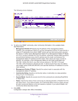
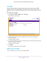
GS752TP, GS728TP, and GS728TPP Gigabit Smart Switches The following screen displays: 2. To add a new SNMP community, enter community information in the available fields described below. • Management Station IP. Specify the IP address of the management station. Together, the management station IP and the management station IP mask denote a range of IP addresses from which SNMP clients can use that community to access this device. If either value (Management Station IP or Management Station IP Mask) is 0.0.0.0, access is allowed from any IP address. Otherwise, bitwise AND operations are performed between every client's address and the mask, and between the management station IP address and the mask. If the values are equal, access is allowed. For example, if the management station IP and mask parameters are 192.168.1.0/255.255.255.0, any client whose address is 192.168.1.0 through 192.168.1.255 (inclusive) is allowed access. To allow access from only one station, use a Mask value of 255.255.255.255, and use that machine's IP address for as the client address. • Management Station IP Mask. Specify the subnet mask to associate with the management station IP address. • Community String. Specify a community name. A valid entry is a case-sensitive string of up to 16 characters. • Access Mode. Specify the access level for this community by selecting Read/Write or Read Only. • Status. Specify the status of this community by selecting Enable or Disable from the pull down menu. If you select Enable, the Community Name must be unique among all valid Community Names or the set request is rejected. If you select Disable, the Community Name becomes invalid. 3. Click ADD. Configuration changes take effect immediately. Configuring System Information 51
-
 1
1 -
2
-
3
-
4
-
5
-
6
-
7
-
8
-
9
-
10
-
11
-
12
-
13
-
14
-
15
-
16
-
17
-
18
-
19
-
20
-
21
-
22
-
23
-
24
-
25
-
26
-
27
-
28
-
29
-
30
-
31
-
32
-
33
-
34
-
35
-
36
-
37
-
38
-
39
-
40
-
41
-
42
-
43
-
44
-
45
-
 46
46 -
 47
47 -
 48
48 -
 49
49 -
 50
50 -
 51
51 -
 52
52 -
 53
53 -
 54
54 -
 55
55 -
 56
56 -
57
-
58
-
59
-
60
-
61
-
62
-
63
-
64
-
65
-
66
-
67
-
68
-
69
-
70
-
71
-
72
-
73
-
74
-
75
-
76
-
77
-
78
-
79
-
80
-
81
-
82
-
83
-
84
-
85
-
86
-
87
-
88
-
89
-
90
-
91
-
92
-
93
-
94
-
95
-
96
-
97
-
98
-
99
-
100
-
101
-
102
-
103
-
104
-
105
-
106
-
107
-
108
-
109
-
110
-
111
-
112
-
113
-
114
-
115
-
116
-
117
-
118
-
119
-
120
-
121
-
122
-
123
-
124
-
125
-
126
-
127
-
128
-
129
-
130
-
131
-
132
-
133
-
134
-
135
-
136
-
137
-
138
-
139
-
140
-
141
-
142
-
143
-
144
-
145
-
146
-
147
-
148
-
149
-
150
-
151
-
152
-
153
-
154
-
155
-
156
-
157
-
158
-
159
-
160
-
161
-
162
-
163
-
164
-
165
-
166
-
167
-
168
-
169
-
170
-
171
-
172
-
173
-
174
-
175
-
176
-
177
-
178
-
179
-
180
-
181
-
182
-
183
-
184
-
185
-
186
-
187
-
188
-
189
-
190
-
191
-
192
-
193
-
194
-
195
-
196
-
197
-
198
-
199
-
200
-
201
-
202
-
203
-
204
-
205
-
206
-
207
-
208
-
209
-
210
-
211
-
212
-
213
-
214
-
215
-
216
-
217
-
218
-
219
-
220
-
221
-
222
-
223
-
224
-
225
-
226
-
227
-
228
-
229
-
230
-
231
-
232
-
233
-
234
-
235
-
236
-
237
-
238
-
239
-
240
-
241
-
242
-
243
-
244
-
245
-
246
-
247
-
248
-
249
-
250
-
251
-
252
-
253
-
254
-
255
-
256
-
257
-
258
-
259
-
260
-
261
-
262
-
263
-
264
-
265
-
266
-
267
-
268
-
269
-
270
-
271
-
272
-
273
-
274
-
275
 |
 |
