Netgear GS728TPP GS728TP/GS728TPP/GS752TP Software Administration Manual - Page 255
Sample VLAN Configuration, In the Port PVID Configuration screen see
 |
View all Netgear GS728TPP manuals
Add to My Manuals
Save this manual to your list of manuals |
Page 255 highlights
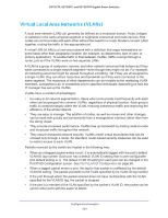
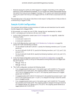
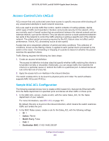
GS752TP, GS728TP, and GS728TPP Gigabit Smart Switches • Packets leaving the switch are either tagged or untagged, depending on the setting for that port's VLAN membership properties. A U for a given port means that packets leaving the switch from that port are untagged. Inversely, a T for a given port means that packets leaving the switch from that port are tagged with the VLAN ID that is associated with the port. The example given in this section describes a wide range of configurations to help provide an understanding of tagged VLANs. Sample VLAN Configuration This example demonstrates several scenarios of VLAN use and describes how the switch handles tagged and untagged traffic. In this example, you create two new VLANs, change the port membership for default VLAN 1, and assign port members to the two new VLANs: 1. In the VLAN Configuration screen (see VLAN Configuration on page 82), create the following VLANs: • A VLAN with VLAN ID 10 • A VLAN with VLAN ID 20 2. In the VLAN Membership screen (see VLAN Membership Configuration on page 84), specify the VLAN membership as follows: • For the default VLAN with VLAN ID 1, specify the following members: port 7 (U) and port 8 (U). • For the VLAN with VLAN ID 10, specify the following members: port 1 (U), port 2 (U), and port 3 (T). • For the VLAN with VLAN ID 20, specify the following members: port 4 (U), port 5 (T), and port 6 (U). 3. In the Port PVID Configuration screen (see Port VLAN ID Configuration on page 85), specify the PVID for ports g1 and g4 so that packets entering these ports are tagged with the port VLAN ID: • Port g1. PVID 10 • Port g4. PVID 20 4. This VLAN configuration produces the following results: • If an untagged packet enters port 1, the switch tags it with VLAN ID 10. The packet has access to port 2 and port 3. The outgoing packet is stripped of its tag to leave port 2 as an untagged packet. For port 3, the outgoing packet leaves as a tagged packet with VLAN ID 10. • If a tagged packet with VLAN ID 10 enters port 3, the packet has access to port 1 and port 2. If the packet leaves port 1 or port 2, it is stripped of its tag to leave the switch as an untagged packet. • If an untagged packet enters port 4, the switch tags it with VLAN ID 20. The packet has access to port 5 and port 6. The outgoing packet is stripped of its tag to become an untagged packet as it leaves port 6. For port 5, the outgoing packet leaves as a tagged packet with VLAN ID 20. Configuration Examples 255
-
 1
1 -
2
-
3
-
4
-
5
-
6
-
7
-
8
-
9
-
10
-
11
-
12
-
13
-
14
-
15
-
16
-
17
-
18
-
19
-
20
-
21
-
22
-
23
-
24
-
25
-
26
-
27
-
28
-
29
-
30
-
31
-
32
-
33
-
34
-
35
-
36
-
37
-
38
-
39
-
40
-
41
-
42
-
43
-
44
-
45
-
46
-
47
-
48
-
49
-
50
-
51
-
52
-
53
-
54
-
55
-
56
-
57
-
58
-
59
-
60
-
61
-
62
-
63
-
64
-
65
-
66
-
67
-
68
-
69
-
70
-
71
-
72
-
73
-
74
-
75
-
76
-
77
-
78
-
79
-
80
-
81
-
82
-
83
-
84
-
85
-
86
-
87
-
88
-
89
-
90
-
91
-
92
-
93
-
94
-
95
-
96
-
97
-
98
-
99
-
100
-
101
-
102
-
103
-
104
-
105
-
106
-
107
-
108
-
109
-
110
-
111
-
112
-
113
-
114
-
115
-
116
-
117
-
118
-
119
-
120
-
121
-
122
-
123
-
124
-
125
-
126
-
127
-
128
-
129
-
130
-
131
-
132
-
133
-
134
-
135
-
136
-
137
-
138
-
139
-
140
-
141
-
142
-
143
-
144
-
145
-
146
-
147
-
148
-
149
-
150
-
151
-
152
-
153
-
154
-
155
-
156
-
157
-
158
-
159
-
160
-
161
-
162
-
163
-
164
-
165
-
166
-
167
-
168
-
169
-
170
-
171
-
172
-
173
-
174
-
175
-
176
-
177
-
178
-
179
-
180
-
181
-
182
-
183
-
184
-
185
-
186
-
187
-
188
-
189
-
190
-
191
-
192
-
193
-
194
-
195
-
196
-
197
-
198
-
199
-
200
-
201
-
202
-
203
-
204
-
205
-
206
-
207
-
208
-
209
-
210
-
211
-
212
-
213
-
214
-
215
-
216
-
217
-
218
-
219
-
220
-
221
-
222
-
223
-
224
-
225
-
226
-
227
-
228
-
229
-
230
-
231
-
232
-
233
-
234
-
235
-
236
-
237
-
238
-
239
-
240
-
241
-
242
-
243
-
244
-
245
-
246
-
247
-
248
-
249
-
 250
250 -
 251
251 -
 252
252 -
 253
253 -
 254
254 -
 255
255 -
 256
256 -
 257
257 -
 258
258 -
 259
259 -
 260
260 -
261
-
262
-
263
-
264
-
265
-
266
-
267
-
268
-
269
-
270
-
271
-
272
-
273
-
274
-
275
 |
 |