Netgear GS728TPP GS728TP/GS728TPP/GS752TP Software Administration Manual - Page 82
VLANs, VLAN Configuration
 |
View all Netgear GS728TPP manuals
Add to My Manuals
Save this manual to your list of manuals |
Page 82 highlights
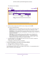
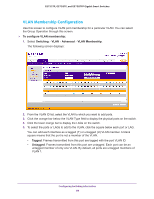
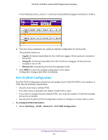
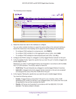
GS752TP, GS728TP, and GS728TPP Gigabit Smart Switches VLANs Adding virtual LAN (VLAN) support to a Layer 2 switch offers some of the benefits of both bridging and routing. Like a bridge, a VLAN switch forwards traffic based on the Layer 2 header, which is fast. Like a router, it partitions the network into logical segments, which provides better administration, security, and management of multicast traffic. By default, all ports on the switch are in the same broadcast domain. VLANs electronically separate ports on the same switch into separate broadcast domains so that broadcast packets are not sent to all the ports on a single switch. When you use a VLAN, users are grouped by logical function instead of physical location. Each VLAN in a network has an associated VLAN ID, which displays in the IEEE 802.1Q tag in the Layer 2 header of packets transmitted on a VLAN. An end station might omit the tag, or the VLAN portion of the tag, in which case the first switch port to receive the packet can either reject it or insert a tag using its default VLAN ID. A given port can handle traffic for more than one VLAN, but it can support only one default VLAN ID. From the VLAN menu, you can access the features described in the following sections: • VLAN Configuration • VLAN Membership Configuration • Port VLAN ID Configuration VLAN Configuration Use the VLAN Configuration screen to define VLAN groups stored in the VLAN membership table. The switch supports up to 256 VLANs. VLAN 1 is created by default, and all ports are untagged members. To configure VLANs: 1. Select Switching VLAN Basic VLAN Configuration. Configuring Switching Information 82
-
 1
1 -
2
-
3
-
4
-
5
-
6
-
7
-
8
-
9
-
10
-
11
-
12
-
13
-
14
-
15
-
16
-
17
-
18
-
19
-
20
-
21
-
22
-
23
-
24
-
25
-
26
-
27
-
28
-
29
-
30
-
31
-
32
-
33
-
34
-
35
-
36
-
37
-
38
-
39
-
40
-
41
-
42
-
43
-
44
-
45
-
46
-
47
-
48
-
49
-
50
-
51
-
52
-
53
-
54
-
55
-
56
-
57
-
58
-
59
-
60
-
61
-
62
-
63
-
64
-
65
-
66
-
67
-
68
-
69
-
70
-
71
-
72
-
73
-
74
-
75
-
76
-
 77
77 -
 78
78 -
 79
79 -
 80
80 -
 81
81 -
 82
82 -
 83
83 -
 84
84 -
 85
85 -
 86
86 -
 87
87 -
88
-
89
-
90
-
91
-
92
-
93
-
94
-
95
-
96
-
97
-
98
-
99
-
100
-
101
-
102
-
103
-
104
-
105
-
106
-
107
-
108
-
109
-
110
-
111
-
112
-
113
-
114
-
115
-
116
-
117
-
118
-
119
-
120
-
121
-
122
-
123
-
124
-
125
-
126
-
127
-
128
-
129
-
130
-
131
-
132
-
133
-
134
-
135
-
136
-
137
-
138
-
139
-
140
-
141
-
142
-
143
-
144
-
145
-
146
-
147
-
148
-
149
-
150
-
151
-
152
-
153
-
154
-
155
-
156
-
157
-
158
-
159
-
160
-
161
-
162
-
163
-
164
-
165
-
166
-
167
-
168
-
169
-
170
-
171
-
172
-
173
-
174
-
175
-
176
-
177
-
178
-
179
-
180
-
181
-
182
-
183
-
184
-
185
-
186
-
187
-
188
-
189
-
190
-
191
-
192
-
193
-
194
-
195
-
196
-
197
-
198
-
199
-
200
-
201
-
202
-
203
-
204
-
205
-
206
-
207
-
208
-
209
-
210
-
211
-
212
-
213
-
214
-
215
-
216
-
217
-
218
-
219
-
220
-
221
-
222
-
223
-
224
-
225
-
226
-
227
-
228
-
229
-
230
-
231
-
232
-
233
-
234
-
235
-
236
-
237
-
238
-
239
-
240
-
241
-
242
-
243
-
244
-
245
-
246
-
247
-
248
-
249
-
250
-
251
-
252
-
253
-
254
-
255
-
256
-
257
-
258
-
259
-
260
-
261
-
262
-
263
-
264
-
265
-
266
-
267
-
268
-
269
-
270
-
271
-
272
-
273
-
274
-
275
 |
 |