Netgear GS748Tv4 GS748Tv4 Software Administration Manual - Page 193
Dst L4 Port, Service Type, Delete, Cancel, Notification Mode, Apply
 |
View all Netgear GS748Tv4 manuals
Add to My Manuals
Save this manual to your list of manuals |
Page 193 highlights
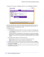
GS748T Smart Switch Software Administration Manual • Dst L4 Port. Requires a packet's TCP/UDP destination port to match the port listed here. Complete one of the following fields: • Destination L4 Keyword: Select the desired L4 keyword from a list of destination ports on which the rule can be based. • Destination L4 Port Number: If the destination L4 keyword is Other, enter a user-defined Port ID by which packets are matched to the rule. • Service Type. Choose one of the Service Type match conditions for the extended IP ACL rule. The possible values are IP DSCP, IP precedence, and IP TOS, which are alternative ways of specifying a match criterion for the same Service Type field in the IP header, however each uses a different user notation. After you select the service type, specify the value associated with the type. • IP DSCP: Specify the IP DiffServ Code Point (DSCP) value. The DSCP is defined as the high-order six bits of the Service Type octet in the IP header. Select an IP DSCP value from the menu. To specify a numeric value in the available field, select Other from the menu and type an integer from 0 to 63 in the field. • IP Precedence: The IP Precedence field in a packet is defined as the high-order three bits of the Service Type octet in the IP header. This is an optional configuration. Enter an integer from 0 to 7. • IP TOS Bits: Matches on the Type of Service bits in the IP header when checked. In the first TOS field, specify the two-digit hexadecimal TOS number. The second field is for the TOS Mask, which specifies the bit positions that are used for comparison against the IP TOS field in a packet. The TOS Mask value is a two-digit hexadecimal number from 00 to ff, representing an inverted (i.e., wildcard) mask. The zero-valued bits in the TOS Mask denote the bit positions in the TOS Bits value that are used for comparison against the IP TOS field of a packet. For example, to check for an IP TOS value having bits 7 and 5 set and bit 1 clear, where bit 7 is most significant, use a TOS Bits value of a0 and a TOS Mask of 00. 3. To delete an IP ACL rule, select the check box associated with the rule, and then click Delete. 4. Click Cancel to cancel the configuration on the screen and reset the data on the screen to the latest value of the switch. 5. To modify an existing IP Extended ACL rule, click the Rule ID. The number is a hyperlink to the Extended ACL Rule Configuration page. If the rule is Deny, you can specify the CPU Notification Mode. • Enable. No power is supplied to the port. • Disable. When a packet matches the ACL rule, the CPU is not notified, and the port continues to provide power. 6. If you modify the rule, click Apply to submit the changes to the switch. Chapter 5: Managing Device Security | 193
-
 1
1 -
2
-
3
-
4
-
5
-
6
-
7
-
8
-
9
-
10
-
11
-
12
-
13
-
14
-
15
-
16
-
17
-
18
-
19
-
20
-
21
-
22
-
23
-
24
-
25
-
26
-
27
-
28
-
29
-
30
-
31
-
32
-
33
-
34
-
35
-
36
-
37
-
38
-
39
-
40
-
41
-
42
-
43
-
44
-
45
-
46
-
47
-
48
-
49
-
50
-
51
-
52
-
53
-
54
-
55
-
56
-
57
-
58
-
59
-
60
-
61
-
62
-
63
-
64
-
65
-
66
-
67
-
68
-
69
-
70
-
71
-
72
-
73
-
74
-
75
-
76
-
77
-
78
-
79
-
80
-
81
-
82
-
83
-
84
-
85
-
86
-
87
-
88
-
89
-
90
-
91
-
92
-
93
-
94
-
95
-
96
-
97
-
98
-
99
-
100
-
101
-
102
-
103
-
104
-
105
-
106
-
107
-
108
-
109
-
110
-
111
-
112
-
113
-
114
-
115
-
116
-
117
-
118
-
119
-
120
-
121
-
122
-
123
-
124
-
125
-
126
-
127
-
128
-
129
-
130
-
131
-
132
-
133
-
134
-
135
-
136
-
137
-
138
-
139
-
140
-
141
-
142
-
143
-
144
-
145
-
146
-
147
-
148
-
149
-
150
-
151
-
152
-
153
-
154
-
155
-
156
-
157
-
158
-
159
-
160
-
161
-
162
-
163
-
164
-
165
-
166
-
167
-
168
-
169
-
170
-
171
-
172
-
173
-
174
-
175
-
176
-
177
-
178
-
179
-
180
-
181
-
182
-
183
-
184
-
185
-
186
-
187
-
 188
188 -
 189
189 -
 190
190 -
 191
191 -
 192
192 -
 193
193 -
 194
194 -
 195
195 -
 196
196 -
 197
197 -
 198
198 -
199
-
200
-
201
-
202
-
203
-
204
-
205
-
206
-
207
-
208
-
209
-
210
-
211
-
212
-
213
-
214
-
215
-
216
-
217
-
218
-
219
-
220
-
221
-
222
-
223
-
224
-
225
-
226
-
227
-
228
-
229
-
230
-
231
-
232
-
233
-
234
-
235
-
236
-
237
-
238
-
239
-
240
-
241
-
242
-
243
-
244
-
245
-
246
-
247
-
248
-
249
-
250
-
251
-
252
-
253
-
254
-
255
-
256
-
257
-
258
-
259
-
260
-
261
-
262
-
263
-
264
-
265
-
266
-
267
-
268
-
269
-
270
-
271
-
272
-
273
 |
 |
