Panasonic WJ-HD716/1000 Installation Guide - Page 17
HDD indicator [HDD1 to HDD4]
 |
View all Panasonic WJ-HD716/1000 manuals
Add to My Manuals
Save this manual to your list of manuals |
Page 17 highlights
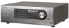
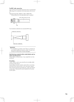
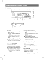
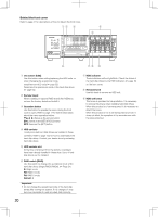
u Maintenance port The maintenance port that can be used for connection with a PC is provided inside the cover. Do not use for any operation other than maintenance. i HDD indicator [HDD1 to HDD4] STS (status): Indicates the operational statuses of the respective hard disk drive. Lights green: Indicates that the power of the respective hard disk drive (formatted) is on. Blinks green: Indicates that the respective hard disk drive is for playback use only. (Recording is unavailable using the respective hard disk drive.) Blinks orange: Indicates that the respective hard disk drive is currently being formatted. Lights red: Indicates that formatting of the respective hard disk drive has failed. Off: Indicates that the power of the respective hard disk drive is off, or that the hard disk drive is not connected/recognized. A/F (HDD access/failure): Indicates the status (access/ failure) of the respective hard disk drive. Blinks green: Indicates that the respective hard disk drive is being accessed. Lights red: The respective built-in hard disk drive is faulty (which can be recovered by replacing the hard disk drive). In the RAID 5 mode, it indicates that the respective hard disk drive is the first faulty drive. In the RAID 6 mode, it indicates that the respective hard disk drives are the first and second faulty drive. Blinks red: The respective built-in hard disk drive is faulty (which cannot be recovered even by replacing the hard disk drive). In the RAID 5 mode, it indicates that the respective hard disk drive is the second faulty drive. In the RAID 6 mode, it indicates that the respective hard disk drive is the third faulty drive. Lights red and orange alternately: Indicates that the respective hard disk drive is currently being recovered in the RAID 5/RAID 6 mode. (It may appear that the indicator lights orange when recovery is being processed at high speed.) Off: Indicates that the respective hard disk drive is not being accessed. Important: When operating in the RAID5/RAID6 mode and the HDD indicator lights red, replace the faulty hard disk drive promptly. Contact your dealer for replacement of hard disk drives. In the RAID 5 mode: When 2 or more HDD indicators light/blink red, it is impossible to recover data on the faulty hard disk. In the RAID 6 mode: When 3 or more HDD indicators light/blink red, it is impossible to recover data on the faulty hard disk. o Monitor operation button [MONITOR] button: Press this button to change the monitor to be operated. The monitor number will light to indicate the monitor currently being selected. [SEQ] button: Press this button to start/stop the sequence. Lights green: During sequence display [OSD] button: Press this button to display/hide information such as the camera title. [MULTI SCREEN] button: Every pressing this button to change the display pattern of multi-screen. !0 Playback control function button [GOTO LAST] button: Press this button to jump the playback point to the top of the latest recorded image. [GOTO DATE] button: Press this button to designate time and date of recorded images to be played. [SEARCH] button: Press this button to play recorded images after searching recording events. Lights green: During search playback [COPY] button: Press this button to display the menu on which it is possible to copy recorded images onto a DVD (when using an optional DVD drive) or a SDHC/ SD memory card. (☞ Operating Instructions (PDF)) !1 [SUB MENU] button Press this button to display the submenu used for cam- era operation and the electronic zoom. (☞ Operating Instructions (PDF)) !2 Menu operation button Arrows button: Use this button to move the cursor on the setup menu, the search menu, etc. [SETUP/ESC] button: Hold down this button to display the setup menu. When the setup menu is being displayed, press this button to go back to the previous page. [SET] button: Press this button to determine the edited settings on the setup menu. This button also can be used to turn the alarm suspension on/off. (☞ Operating Instructions (PDF)) !3 Mouse connection port [MOUSE] Use this port to connect a USB mouse (commercially available). (No device other than a mouse can be connected.) * It is impossible to connect a mouse to the mouse connection port if the connector from the mouse is upside down. When it is hard to connect, check the upside down position of the connector from the mouse. !4 SDHC/SD memory card slot/External output connector (AUDIO OUT, VIDEO OUT) The video output connector (RCA pin jack) to be used for output to a VCR, audio output connector (RCA pin jack) and SDHC/SD memory card slot are provided inside the cover. !5 Built-in DVD It is possible to install an optional built-in DVD (WJ-HDB611). 17
-
 1
1 -
2
-
3
-
4
-
5
-
6
-
7
-
8
-
9
-
10
-
11
-
 12
12 -
 13
13 -
 14
14 -
 15
15 -
 16
16 -
 17
17 -
 18
18 -
 19
19 -
 20
20 -
 21
21 -
 22
22 -
23
-
24
-
25
-
26
-
27
-
28
-
29
-
30
-
31
-
32
-
33
-
34
-
35
-
36
-
37
-
38
-
39
-
40
-
41
-
42
-
43
-
44
-
45
-
46
-
47
-
48
-
49
-
50
-
51
-
52
-
53
-
54
-
55
-
56
-
57
-
58
-
59
-
60
-
61
-
62
-
63
-
64
-
65
-
66
-
67
-
68
-
69
-
70
-
71
-
72
-
73
-
74
-
75
-
76
-
77
-
78
-
79
-
80
-
81
-
82
-
83
-
84
-
85
-
86
-
87
-
88
-
89
-
90
-
91
-
92
-
93
-
94
-
95
-
96
-
97
-
98
-
99
-
100
-
101
-
102
-
103
-
104
-
105
-
106
-
107
-
108
-
109
-
110
-
111
-
112
-
113
-
114
-
115
-
116
-
117
-
118
-
119
-
120
-
121
-
122
-
123
-
124
-
125
-
126
-
127
-
128
-
129
-
130
-
131
-
132
-
133
-
134
-
135
-
136
-
137
-
138
-
139
-
140
-
141
-
142
-
143
-
144
-
145
-
146
-
147
-
148
-
149
-
150
-
151
-
152
-
153
-
154
-
155
-
156
 |
 |