Panasonic WJ-HD716/1000 Installation Guide - Page 50
Time and polarities of the ALARM/CONTROL terminal and the ALARM
 |
View all Panasonic WJ-HD716/1000 manuals
Add to My Manuals
Save this manual to your list of manuals |
Page 50 highlights
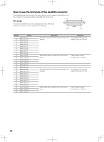
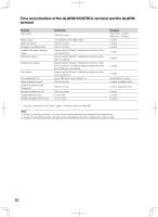
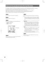
Time and polarities of the ALARM/CONTROL terminal and the ALARM terminal Terminal Alarm input Alarm output Alarm reset input Emergency recording input Available disk space warning output HDD error output Camera error output Error output Time adjustment I/O Alarm suspension input External recording mode changeover Sequence switchover I/O Outage detection input Outage processing end output Active time 100 ms or more The set time on the setup menu 100 ms or more 100 ms or more Duration set for "Buzzer"* starting from the time of the error occurrence Duration set for "Buzzer"* starting from the time of the error occurrence Duration set for "Buzzer"* starting from the time of the error occurrence, or until the camera is reset (from the time of the error occurrence). Duration set for "Buzzer"* starting from the time of the error occurrence Input: 100 ms or more, Output: 1 s 100 ms or more 100 ms or more 100 ms or more 5 s or more 10 s or more Remarks When N.O.: L active When N.C.: H active L active L active L active L active L active L active L active Input/Output: L active L active, judged by level L active, judged by level L active L active H active * "Buzzer" can be set on the "Basic" page of the setup menu. (☞ Page 65) Note: • During "L active (Low active)", the logic will be implemented when the voltage level of signal is low. • During "H active (High active)", the logic will be implemented when the voltage level of signal is high. 50
-
 1
1 -
2
-
3
-
4
-
5
-
6
-
7
-
8
-
9
-
10
-
11
-
12
-
13
-
14
-
15
-
16
-
17
-
18
-
19
-
20
-
21
-
22
-
23
-
24
-
25
-
26
-
27
-
28
-
29
-
30
-
31
-
32
-
33
-
34
-
35
-
36
-
37
-
38
-
39
-
40
-
41
-
42
-
43
-
44
-
 45
45 -
 46
46 -
 47
47 -
 48
48 -
 49
49 -
 50
50 -
 51
51 -
 52
52 -
 53
53 -
 54
54 -
 55
55 -
56
-
57
-
58
-
59
-
60
-
61
-
62
-
63
-
64
-
65
-
66
-
67
-
68
-
69
-
70
-
71
-
72
-
73
-
74
-
75
-
76
-
77
-
78
-
79
-
80
-
81
-
82
-
83
-
84
-
85
-
86
-
87
-
88
-
89
-
90
-
91
-
92
-
93
-
94
-
95
-
96
-
97
-
98
-
99
-
100
-
101
-
102
-
103
-
104
-
105
-
106
-
107
-
108
-
109
-
110
-
111
-
112
-
113
-
114
-
115
-
116
-
117
-
118
-
119
-
120
-
121
-
122
-
123
-
124
-
125
-
126
-
127
-
128
-
129
-
130
-
131
-
132
-
133
-
134
-
135
-
136
-
137
-
138
-
139
-
140
-
141
-
142
-
143
-
144
-
145
-
146
-
147
-
148
-
149
-
150
-
151
-
152
-
153
-
154
-
155
-
156
 |
 |