Panasonic WJ-HD716/1000 Installation Guide - Page 46
Connection for the auto time adjustment function 1, Connection for the auto time adjustment function
 |
View all Panasonic WJ-HD716/1000 manuals
Add to My Manuals
Save this manual to your list of manuals |
Page 46 highlights
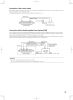
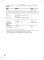
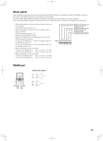
Connection for the auto time adjustment function (1) When "Master" is set for "Auto time adjustment" on the [Time & date] tab under the "Basic" page of the setup menu "Time adjustment signal output" becomes available and the clock of this recorder will be applied to other devices. The time adjustment signal output will be generated from pin no. 20 (time adjustment I/O) at the time set for "Activation time" (Signal ground) (Time adjustment signal output) 13 20 Terminal of the other device Output for the indicators on the front panel Signal ground Sensor signal input Alarm input Alarm reset input Series recording output Time adjustment signal input Signal ground Alarm output Alarm reset output Alarm recording During recording Disk Buzzer output System error output Thermal error output Time adjustment signal output Series recording output ALARM/CONTROL Connection for the auto time adjustment function (2) When "Slave" is set for "Auto adjustment time" on the [Time & date] tab under the "Basic"page of the setup menu "Time adjustment signal input" becomes available and the clock of the other device will be applied to this recorder. When a signal output from the other device is supplied to the time adjustment I/O terminals (pin no. 20) 15 minutes before/after the time set for "Activation time", the clock of the recorder will be set to the time set for "Activation time". Example: When "15:00" is set for "Activation time" • Signal is supplied at 2:50:00 (hour:minute:second) pm → Set at 3:00:00 pm • Signal input supplied at 3:14:45 pm → Set at 3:00:00 pm • Signal is supplied at 3:20:00 pm → Time will not be adjusted. (Signal ground) (Time adjustment signal output) 13 20 Terminal of the other device Output for the indicators on the front panel Signal ground Sensor signal input Alarm input Alarm reset input Series recording output Time adjustment signal input Signal ground Alarm output Alarm reset output Alarm recording During recording Disk Buzzer output System error output Thermal error output Time adjustment signal output Series recording output ALARM/CONTROL Important: • When "Slave" is selected, the clock will not be adjusted during event recording or emergency recording. 46
-
 1
1 -
2
-
3
-
4
-
5
-
6
-
7
-
8
-
9
-
10
-
11
-
12
-
13
-
14
-
15
-
16
-
17
-
18
-
19
-
20
-
21
-
22
-
23
-
24
-
25
-
26
-
27
-
28
-
29
-
30
-
31
-
32
-
33
-
34
-
35
-
36
-
37
-
38
-
39
-
40
-
 41
41 -
 42
42 -
 43
43 -
 44
44 -
 45
45 -
 46
46 -
 47
47 -
 48
48 -
 49
49 -
 50
50 -
 51
51 -
52
-
53
-
54
-
55
-
56
-
57
-
58
-
59
-
60
-
61
-
62
-
63
-
64
-
65
-
66
-
67
-
68
-
69
-
70
-
71
-
72
-
73
-
74
-
75
-
76
-
77
-
78
-
79
-
80
-
81
-
82
-
83
-
84
-
85
-
86
-
87
-
88
-
89
-
90
-
91
-
92
-
93
-
94
-
95
-
96
-
97
-
98
-
99
-
100
-
101
-
102
-
103
-
104
-
105
-
106
-
107
-
108
-
109
-
110
-
111
-
112
-
113
-
114
-
115
-
116
-
117
-
118
-
119
-
120
-
121
-
122
-
123
-
124
-
125
-
126
-
127
-
128
-
129
-
130
-
131
-
132
-
133
-
134
-
135
-
136
-
137
-
138
-
139
-
140
-
141
-
142
-
143
-
144
-
145
-
146
-
147
-
148
-
149
-
150
-
151
-
152
-
153
-
154
-
155
-
156
 |
 |
