Panasonic WJ-HD716/1000 Installation Guide - Page 48
How to use the terminals of the ALARM connector
 |
View all Panasonic WJ-HD716/1000 manuals
Add to My Manuals
Save this manual to your list of manuals |
Page 48 highlights
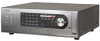
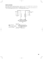
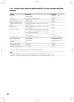
How to use the terminals of the ALARM connector These terminals are used to connect the alarm devices, such as sensors, door switches, etc. The connector to be used should be compatible with the pin array. 13 1 Pin array The pin array is different from other digital disk recorders. Make sure that the connection is correct referring to the following. Alarm 25 14 Pin No. Signal 1 Alarm input 1 2 Alarm input 2 3 Alarm input 3 4 Alarm input 4 5 Alarm input 5 6 Alarm input 6 7 Alarm input 7 8 Alarm input 8 9 Alarm output 1 10 Alarm output 2 11 Alarm output 3 12 Alarm output 4 13 Signal ground 14 Signal ground 15 Alarm input 9 16 Alarm input 10 17 Alarm input 11 18 Alarm input 12 19 Alarm input 13 20 Alarm input 14 21 Alarm input 15 22 Alarm input 16 23 Alarm output 5 24 Alarm output 6 25 Alarm output 7 Operation Event actions will be performed according to the settings. Remarks Non-voltage make contact input/5 V pull-up/-100 mA Alarm signal will be supplied at an event occurrence Open collector output 24 V DC max., -100 mA Event actions will be performed according to the Non-voltage make contact settings. input/5 V pull-up/-100 mA Alarm signal will be supplied at an event occurrence Open collector output 24 V DC max., -100 mA 48
-
 1
1 -
2
-
3
-
4
-
5
-
6
-
7
-
8
-
9
-
10
-
11
-
12
-
13
-
14
-
15
-
16
-
17
-
18
-
19
-
20
-
21
-
22
-
23
-
24
-
25
-
26
-
27
-
28
-
29
-
30
-
31
-
32
-
33
-
34
-
35
-
36
-
37
-
38
-
39
-
40
-
41
-
42
-
 43
43 -
 44
44 -
 45
45 -
 46
46 -
 47
47 -
 48
48 -
 49
49 -
 50
50 -
 51
51 -
 52
52 -
 53
53 -
54
-
55
-
56
-
57
-
58
-
59
-
60
-
61
-
62
-
63
-
64
-
65
-
66
-
67
-
68
-
69
-
70
-
71
-
72
-
73
-
74
-
75
-
76
-
77
-
78
-
79
-
80
-
81
-
82
-
83
-
84
-
85
-
86
-
87
-
88
-
89
-
90
-
91
-
92
-
93
-
94
-
95
-
96
-
97
-
98
-
99
-
100
-
101
-
102
-
103
-
104
-
105
-
106
-
107
-
108
-
109
-
110
-
111
-
112
-
113
-
114
-
115
-
116
-
117
-
118
-
119
-
120
-
121
-
122
-
123
-
124
-
125
-
126
-
127
-
128
-
129
-
130
-
131
-
132
-
133
-
134
-
135
-
136
-
137
-
138
-
139
-
140
-
141
-
142
-
143
-
144
-
145
-
146
-
147
-
148
-
149
-
150
-
151
-
152
-
153
-
154
-
155
-
156
 |
 |