Panasonic WJ-HD716/1000 Installation Guide - Page 33
Connection of an extension unit
 |
View all Panasonic WJ-HD716/1000 manuals
Add to My Manuals
Save this manual to your list of manuals |
Page 33 highlights
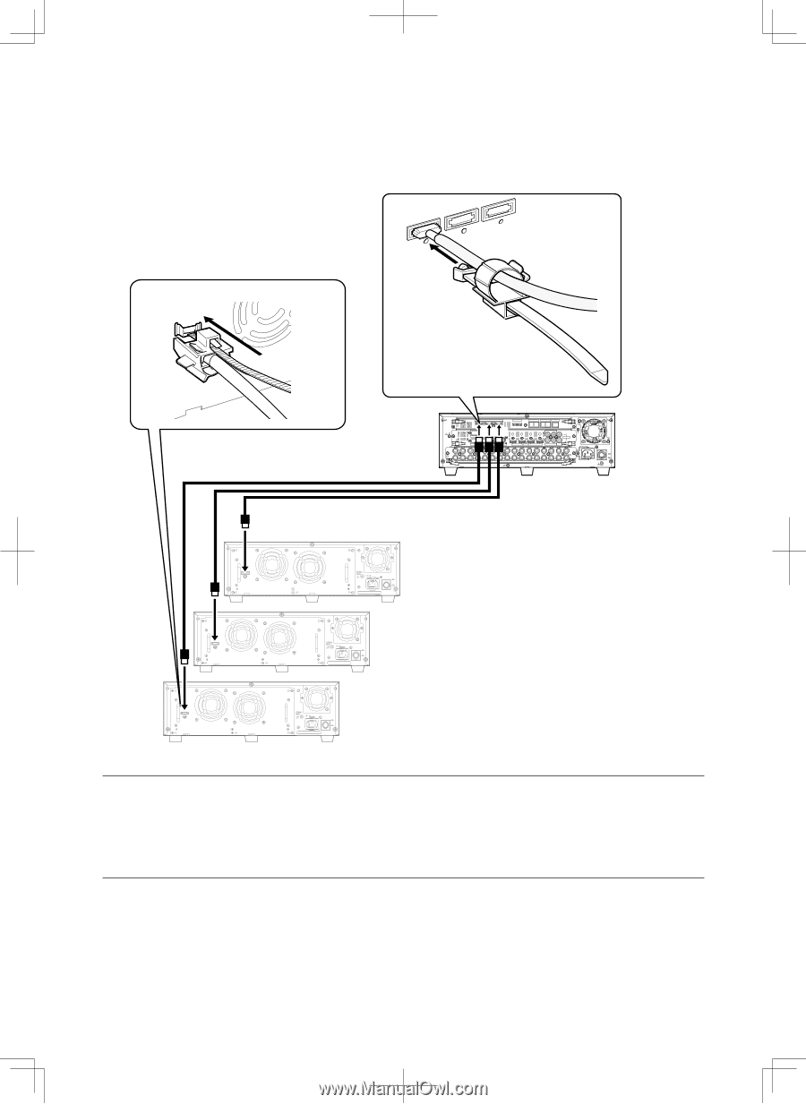
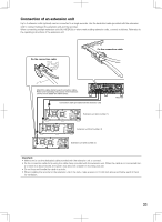
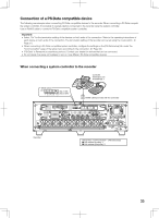
Connection of an extension unit Up to 3 extension units (optional) can be connected to a single recorder. Use the dedicated cable (provided with the extension unit) to connect between the extension unit and the recorder. When connecting multiple extension units (WJ-HDE400) or when newly adding extension units, connect as follows. Refer also to the operating instructions of the extension unit. Fix the connection cable Fix the connection cable Attach the cable clamp to each connection cable. Refer to the operating instructions of the extension unit for how to attach the cable clamp. IN OUT EXT STORAGE MODE DATA 3 2 3 ALARM 1 2 11 MONITOR OUT 2 ALARM/CONTROL OUT-CASCADE-IN 12345678 2 2 1 2 1 CASCADE IN OUT MONITOR OUT(HD) 1 3 1 IN CASCADE OUT 4 2 AUDIO AUDIO IN OUT 16 15 14 13 12 11 10 9 8 7 6 5 4 3 2 1 7 1 OUT 16 15 14 13 12 11 10 9 8 7 6 5 4 3 2 VIDEO POWER ON OFF AC IN SIGNAL GND Recorder Connection cable (provided with the extension unit) Extension unit (Unit number: 1) EXT IN POWER ON OFF EXT IN EXT IN Extension unit (Unit number: 2) POWER ON OFF Extension unit (Unit number: 3) POWER ON OFF Important: • Make sure to use the dedicated cable provided with the extension unit to connect. • Fix the connection cable firmly using the cable clamp provided with the extension unit. When the cable is not connected firm- ly or when it is disconnected, the system may become unstable or recording may fail. • Do not loop and bundle the cable in a circle. • When installing the recorder or the extension unit in the rack, make a space of 1U (44 mm) above and below each of them for ventilation. 33
-
 1
1 -
2
-
3
-
4
-
5
-
6
-
7
-
8
-
9
-
10
-
11
-
12
-
13
-
14
-
15
-
16
-
17
-
18
-
19
-
20
-
21
-
22
-
23
-
24
-
25
-
26
-
27
-
 28
28 -
 29
29 -
 30
30 -
 31
31 -
 32
32 -
 33
33 -
 34
34 -
 35
35 -
 36
36 -
 37
37 -
 38
38 -
39
-
40
-
41
-
42
-
43
-
44
-
45
-
46
-
47
-
48
-
49
-
50
-
51
-
52
-
53
-
54
-
55
-
56
-
57
-
58
-
59
-
60
-
61
-
62
-
63
-
64
-
65
-
66
-
67
-
68
-
69
-
70
-
71
-
72
-
73
-
74
-
75
-
76
-
77
-
78
-
79
-
80
-
81
-
82
-
83
-
84
-
85
-
86
-
87
-
88
-
89
-
90
-
91
-
92
-
93
-
94
-
95
-
96
-
97
-
98
-
99
-
100
-
101
-
102
-
103
-
104
-
105
-
106
-
107
-
108
-
109
-
110
-
111
-
112
-
113
-
114
-
115
-
116
-
117
-
118
-
119
-
120
-
121
-
122
-
123
-
124
-
125
-
126
-
127
-
128
-
129
-
130
-
131
-
132
-
133
-
134
-
135
-
136
-
137
-
138
-
139
-
140
-
141
-
142
-
143
-
144
-
145
-
146
-
147
-
148
-
149
-
150
-
151
-
152
-
153
-
154
-
155
-
156
 |
 |