Panasonic WJ-HD716/1000 Installation Guide - Page 35
When connecting a system controller to the recorder
 |
View all Panasonic WJ-HD716/1000 manuals
Add to My Manuals
Save this manual to your list of manuals |
Page 35 highlights
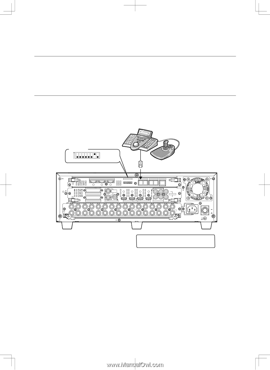
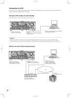
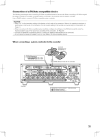
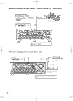
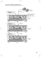
Connection of a PS·Data compatible device The following are examples when connecting PS·Data compatible devices to the recorder. When connecting a PS·Data compatible system controller, it is possible to operate devices connected to the recorder using the system controller. Use an RS485 cable to connect a PS·Data compatible system controller. Important: • Select "On" for the termination setting of the devices on both ends of the connection. Refer to the operating instructions of each device on both ends of the connection. The termination setting of the recorder can be set using the mode switch. (☞ Page 51) • When connecting a PS·Data compatible system controller, configure the settings on the [PS·Data setup] tab under the "Communication" page of the setup menu according to the connection. (☞ Page 93) • "PS·Data" is Panasonic's proprietary protocol. Contact your dealer for devices that can be connected. • Do not assign the same unit address to two or more different PS·Data compatible devices. When connecting a system controller to the recorder Controller Termination: On Unit address: 1 Mode switch ON (No.7: ON) 1 2 3 4 5 6 7 8 (No.8: OFF) RS485 cable (provided with the controller) IN OUT EXT STORAGE MODE DATA RS485(CAMERA) 10/100BASE-T 3 2 ALARM ALARM/CONTROL 1 1 MONITOR OUT 2 OUT-CASCADE-IN 12345678 2 2 1 2 1 CASCADE IN OUT MONITOR OUT(HD) 1 3 1 IN CASCADE OUT 4 2 AUDIO AUDIO IN OUT 16 15 14 13 12 11 10 9 8 7 6 5 4 3 2 1 7 1 OUT 16 15 14 13 12 11 10 9 8 7 6 5 4 3 2 VIDEO POWER ON OFF AC IN SIGNAL GND Recorder Setup menu "Communication" - [PS·Data setup] ■ Unit address (system): 1 ■ Unit address (controller): 2 35
-
 1
1 -
2
-
3
-
4
-
5
-
6
-
7
-
8
-
9
-
10
-
11
-
12
-
13
-
14
-
15
-
16
-
17
-
18
-
19
-
20
-
21
-
22
-
23
-
24
-
25
-
26
-
27
-
28
-
29
-
 30
30 -
 31
31 -
 32
32 -
 33
33 -
 34
34 -
 35
35 -
 36
36 -
 37
37 -
 38
38 -
 39
39 -
 40
40 -
41
-
42
-
43
-
44
-
45
-
46
-
47
-
48
-
49
-
50
-
51
-
52
-
53
-
54
-
55
-
56
-
57
-
58
-
59
-
60
-
61
-
62
-
63
-
64
-
65
-
66
-
67
-
68
-
69
-
70
-
71
-
72
-
73
-
74
-
75
-
76
-
77
-
78
-
79
-
80
-
81
-
82
-
83
-
84
-
85
-
86
-
87
-
88
-
89
-
90
-
91
-
92
-
93
-
94
-
95
-
96
-
97
-
98
-
99
-
100
-
101
-
102
-
103
-
104
-
105
-
106
-
107
-
108
-
109
-
110
-
111
-
112
-
113
-
114
-
115
-
116
-
117
-
118
-
119
-
120
-
121
-
122
-
123
-
124
-
125
-
126
-
127
-
128
-
129
-
130
-
131
-
132
-
133
-
134
-
135
-
136
-
137
-
138
-
139
-
140
-
141
-
142
-
143
-
144
-
145
-
146
-
147
-
148
-
149
-
150
-
151
-
152
-
153
-
154
-
155
-
156
 |
 |