Panasonic WJ-HD716/1000 Installation Guide - Page 38
Cascading connection using HDMI cables
 |
View all Panasonic WJ-HD716/1000 manuals
Add to My Manuals
Save this manual to your list of manuals |
Page 38 highlights
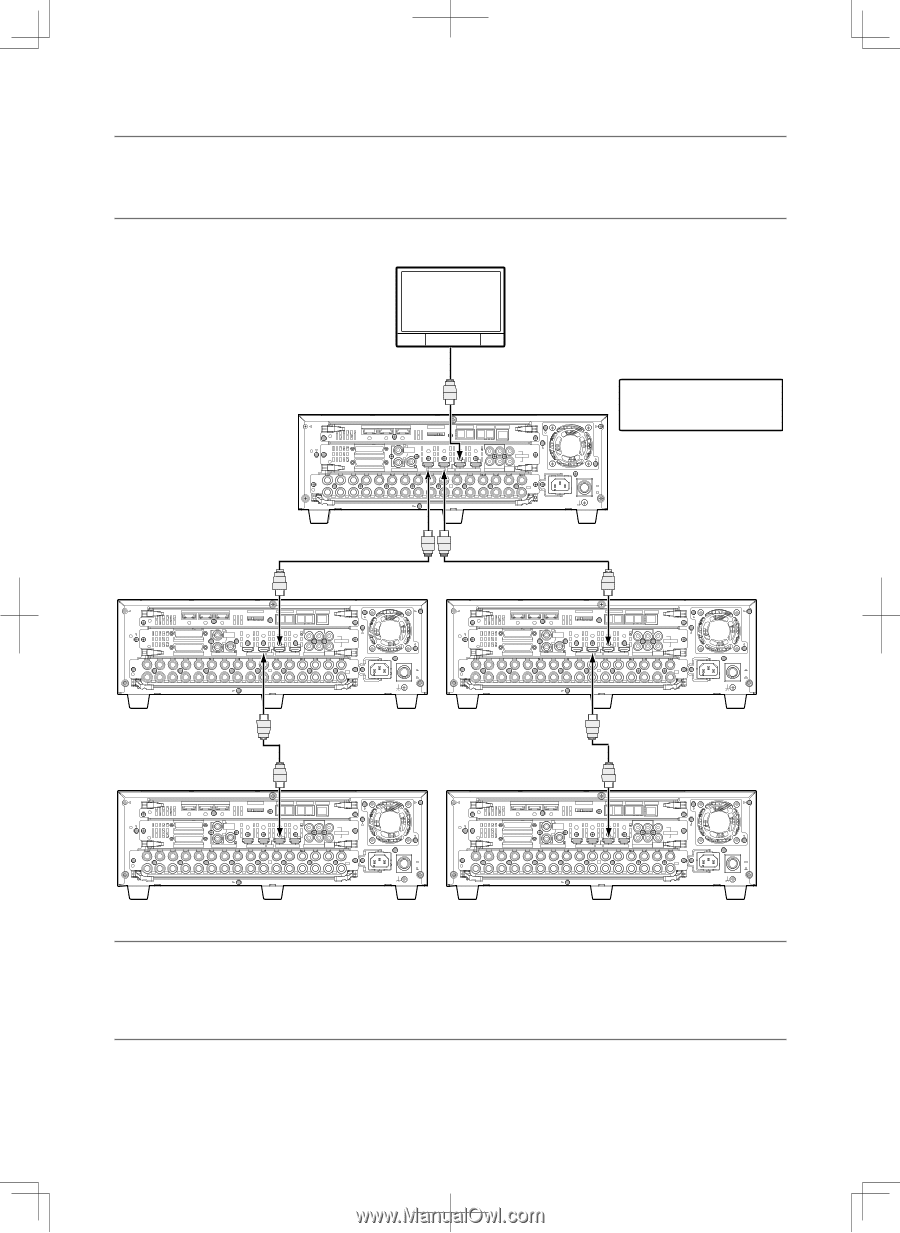
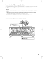
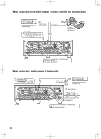
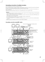
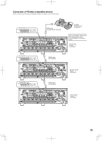
Cascading connection using HDMI cables Important: • Up to 5 recorders and a single system controller can be connected. • Connect the recorder whose unit address (system) is even number to the cascade input 1 connector of the first recorder. Connect the recorder whose unit address (system) is odd number to the cascade input 2 connector of the second recorder. Connect the fourth and fifth recorders to the cascade input 1 connectors of the second and third recorders respectively. Monitor 2 HDMI cable (sold separately) IN OUT EXT STORAGE MODE DATA RS485(CAMERA) 10/100BASE-T 3 2 ALARM ALARM/CONTROL 1 1 MONITOR OUT 2 OUT-CASCADE-IN 12345678 2 2 1 2 1 CASCADE IN OUT MONITOR OUT(HD) 1 3 1 IN CASCADE OUT 4 2 AUDIO AUDIO IN OUT 16 15 14 13 12 11 10 9 8 7 6 5 4 3 2 1 7 1 OUT 16 15 14 13 12 11 10 9 8 7 6 5 4 3 2 VIDEO POWER ON OFF AC IN SIGNAL GND The "Unit address" setting on the [PS·Data setup] tab under "Communication" of the setup menu First recorder System: 1 Controller: 1 Third recorder System: 3 Controller: 3 IN OUT EXT STORAGE MODE DATA RS485(CAMERA) 10/100BASE-T 3 2 ALARM ALARM/CONTROL 1 1 MONITOR OUT 2 OUT-CASCADE-IN 12345678 2 2 1 2 1 CASCADE IN OUT MONITOR OUT(HD) 1 3 1 IN CASCADE OUT 4 2 AUDIO AUDIO IN OUT 16 15 14 13 12 11 10 9 8 7 6 5 4 3 2 1 7 1 OUT 16 15 14 13 12 11 10 9 8 7 6 5 4 3 2 VIDEO POWER ON OFF AC IN SIGNAL GND Second recorder System: 2 Controller: 2 IN OUT EXT STORAGE MODE DATA RS485(CAMERA) 10/100BASE-T 3 2 ALARM ALARM/CONTROL 1 1 MONITOR OUT 2 OUT-CASCADE-IN 12345678 2 2 1 2 1 CASCADE IN OUT MONITOR OUT(HD) 1 3 1 IN CASCADE OUT 4 2 AUDIO AUDIO IN OUT 16 15 14 13 12 11 10 9 8 7 6 5 4 3 2 1 7 1 OUT 16 15 14 13 12 11 10 9 8 7 6 5 4 3 2 VIDEO POWER ON OFF AC IN SIGNAL GND Fifth recorder System: 5 Controller: 5 IN OUT EXT STORAGE MODE DATA RS485(CAMERA) 10/100BASE-T 3 2 ALARM ALARM/CONTROL 1 1 MONITOR OUT 2 OUT-CASCADE-IN 12345678 2 2 1 2 1 CASCADE IN OUT MONITOR OUT(HD) 1 3 1 IN CASCADE OUT 4 2 AUDIO AUDIO IN OUT 16 15 14 13 12 11 10 9 8 7 6 5 4 3 2 1 7 1 OUT 16 15 14 13 12 11 10 9 8 7 6 5 4 3 2 VIDEO POWER ON OFF AC IN SIGNAL GND Fourth recorder System: 4 Controller: 4 IN OUT EXT STORAGE MODE DATA RS485(CAMERA) 10/100BASE-T 3 2 ALARM ALARM/CONTROL 1 1 MONITOR OUT 2 OUT-CASCADE-IN 12345678 2 2 1 2 1 CASCADE IN OUT MONITOR OUT(HD) 1 3 1 IN CASCADE OUT 4 2 AUDIO AUDIO IN OUT 16 15 14 13 12 11 10 9 8 7 6 5 4 3 2 1 7 1 OUT 16 15 14 13 12 11 10 9 8 7 6 5 4 3 2 VIDEO POWER ON OFF AC IN SIGNAL GND Note: • Connection using the DATA port (with RS485 cables) can be made in the same manner as connection using the BNC cables (+ page 37). • When connecting using the HDMI cables, audio will be output together (However, audio will not be output from the audio output connector (RCA pin jack).) • In cascading connection, it may take time to change the monitor display. 38
-
 1
1 -
2
-
3
-
4
-
5
-
6
-
7
-
8
-
9
-
10
-
11
-
12
-
13
-
14
-
15
-
16
-
17
-
18
-
19
-
20
-
21
-
22
-
23
-
24
-
25
-
26
-
27
-
28
-
29
-
30
-
31
-
32
-
 33
33 -
 34
34 -
 35
35 -
 36
36 -
 37
37 -
 38
38 -
 39
39 -
 40
40 -
 41
41 -
 42
42 -
 43
43 -
44
-
45
-
46
-
47
-
48
-
49
-
50
-
51
-
52
-
53
-
54
-
55
-
56
-
57
-
58
-
59
-
60
-
61
-
62
-
63
-
64
-
65
-
66
-
67
-
68
-
69
-
70
-
71
-
72
-
73
-
74
-
75
-
76
-
77
-
78
-
79
-
80
-
81
-
82
-
83
-
84
-
85
-
86
-
87
-
88
-
89
-
90
-
91
-
92
-
93
-
94
-
95
-
96
-
97
-
98
-
99
-
100
-
101
-
102
-
103
-
104
-
105
-
106
-
107
-
108
-
109
-
110
-
111
-
112
-
113
-
114
-
115
-
116
-
117
-
118
-
119
-
120
-
121
-
122
-
123
-
124
-
125
-
126
-
127
-
128
-
129
-
130
-
131
-
132
-
133
-
134
-
135
-
136
-
137
-
138
-
139
-
140
-
141
-
142
-
143
-
144
-
145
-
146
-
147
-
148
-
149
-
150
-
151
-
152
-
153
-
154
-
155
-
156
 |
 |